A floating address plaque is one of the cleanest, most premium-looking ways to display your house number. The numbers or name plate sit away from the wall surface on threaded standoff posts. There is a gap of 15 to 25mm between the back of the plaque and the wall face. During daylight, that gap creates a crisp shadow line around the plaque that gives it a three-dimensional, architectural quality. At night, if the plaque has LED backlighting, the gap glows.
Installing a floating address plaque looks simple. In practice, it requires more care than a flush-mounted plate. The fixing holes must be in the right location. The anchors must be right for the wall material. The fixing holes must be sealed against water ingress. The standoff posts must be tightened to the right torque. And the plaque must be level when you are done.
This guide walks you through every step for the three most common exterior wall types: stucco (Portland cement render), brick, and siding (vinyl, fiber cement, and wood).
Work through the guide for your specific wall type. If you are not sure which type of wall you have, the identification section in the first step will help you.
📥 Download Free: Our Floating Address Plaque Installation Checklist — 18 steps with a tick-box format you can print and take to the wall.
What Is a Floating Address Plaque and Why the Mounting Style Matters
A floating address plaque uses standoff posts to create a gap between the plaque and the wall. The standoff post is a short threaded barrel: one end screws into a wall anchor, the other end passes through the plaque and is secured with a cap nut. The barrel holds the plaque away from the wall face.
The floating gap does more than just look good. It also protects the plaque from the wall. Here is why this matters.
Masonry walls absorb moisture and release it during temperature changes. If a metal plaque is pressed flat against a damp masonry wall, the trapped moisture between the plaque and the wall accelerates corrosion on the back of the plaque. The floating gap allows air to circulate behind the plaque. This prevents moisture trapping and extends the life of the plaque.
On stucco walls, the floating gap also allows the standoff post to absorb minor surface irregularities in the stucco texture. A flat plaque pressed directly onto rough stucco rocks slightly and creates a gap at the edges. The standoff post brings the plaque cleanly forward of the texture, leaving it stable on a level plane.
The floating gap also allows for the thermal expansion of the plaque without the wall constraining it. A 400mm metal plaque can expand by 0.2 to 0.4mm on a hot day. A floating mount allows this movement freely.
Expert Note: When a property maintenance manager at a luxury residential development is reviewing a floating address plaque installation that failed within 18 months (the stainless steel standoff posts showed rust staining on a rendered masonry gate pillar), and asks the materials consultant whether the cement render environment could cause accelerated corrosion of stainless steel standoff hardware that would not be predicted by normal outdoor exposure classification, the corrosivity of the render/masonry environment for metallic fasteners is assessed using the framework in ISO 9223:2012 (Corrosion of Metals and Alloys: Corrosivity of Atmospheres: Classification, Determination and Estimation), the ISO standard specifying the classification of the atmospheric corrosivity of outdoor environments based on the annual mass loss of standard corrosion rate specimens, providing four primary corrosivity categories (C1 to C5 and CX) for ferrous and non-ferrous metals. ISO 9223 identifies two specific aggressive microenvironments that affect metal fasteners in contact with cementitious materials: Chloride ions (Cl minus): if the masonry contains chloride from seawater aggregates, de-icing salts, or coastal exposure, chloride ions in the pore solution attack the passive oxide layer on stainless steel. This causes crevice corrosion at the contact point between the standoff post and the anchor. The classification is C4 to C5 (high to very high corrosivity) for the microenvironment at the masonry contact point, even if the general atmospheric corrosivity is only C2 (low). Sulphur dioxide (SO2): industrial atmospheric SO2 combined with moisture creates sulphurous acid in the stucco pore water, which also attacks zinc-plated carbon steel fasteners rapidly. Assessment: the rust staining came from zinc-plated carbon steel anchor bolts specified by the installation contractor to save cost over A4 stainless steel. The zinc coating in contact with the alkaline cement pore solution (pH 12 to 13) was sacrificed rapidly, exposing the carbon steel core which then corroded. Recommendation: replace all anchor bolts with A4-80 austenitic stainless steel (ISO 3506-1 grade A4), which maintains its passive oxide layer in alkaline cementitious environments and is not susceptible to chloride crevice corrosion within normal wall pH ranges (pH 10 to 13). Atmospheric corrosivity assessment of the masonry microenvironment for standoff address plaque fastener selection follows ISO 9223:2012 (Corrosion of Metals and Alloys: Corrosivity of Atmospheres: Classification, Determination and Estimation), the ISO standard for classifying the corrosivity of environments and microenvironments affecting metallic fasteners and hardware in outdoor construction applications.
Tools and Materials You Need Before You Start
Gather everything before you begin. Stopping mid-installation to find a missing tool is the most common cause of a crooked, badly sealed, or poorly torqued plaque.
Required tools:
- Hammer drill (for stucco and brick installations)
- Standard variable-speed drill driver (for siding installations)
- Tungsten carbide masonry drill bits (in the correct diameter for your anchors: typically 6mm, 8mm, or 10mm)
- HSS (High Speed Steel) or titanium-coated drill bits (for fiber cement and wood siding)
- Spirit level (300mm length minimum)
- Steel tape measure
- Pencil or chalk marker
- Vacuum or rubber bulb pump (to clear drill dust from holes)
- Small paintbrush (to apply sealant around fixing holes)
- Torque limiting screwdriver or adjustable torque wrench (for tightening standoff cap nuts)
- Painter’s tape (for position marking and preventing surface scratches)
- Cotton cloth (for cleaning the wall surface before marking)
Required materials:
- Standoff address plaque with standoff posts, spacers, and cap nuts (supplied by plaque manufacturer)
- Wall anchors (sized correctly for the standoff post diameter: see substrate-specific sections below)
- A4 (grade 316) stainless steel machine screws and cap nuts (if not supplied with the plaque)
- Exterior elastomeric sealant (silicone or polyurethane, ASTM C920 rated, paintable grade if you plan to paint around the fixings)
- Masking tape
- EPDM or rubber washers (to cushion the back of the cap nut against the plaque face surface)
Expert Note: When a custom sign company is preparing an installation pack for a batch of 200 floating stainless steel address plaques to be distributed to homeowners across a new residential development, and the technical writer asks the installation engineer to specify which masonry drill bit designation and geometry to recommend for the carbide-tipped masonry bits included in each installation pack (the bits must drill cleanly through stucco render and penetrate into the concrete block substrate below without cracking the stucco surface), the dimensions, geometry, and quality requirements for carbide-tipped masonry drill bits are specified in DIN 8034:2003 (Carbide-Tipped Masonry Drills: Dimensions), the German DIN standard specifying the dimensional requirements for tungsten carbide-tipped masonry drill bits for use in rotary and hammer drills. DIN 8034 specifies: overall bit length (L): for an 8mm diameter masonry bit: total length 120 to 160mm, working length (fluted section) 80 to 110mm. Cutting tip width (d1): the carbide cutting tip must be wider than the nominal shank diameter by 0.3 to 0.5mm (i.e., for an 8mm shank: tip width 8.3 to 8.5mm). This oversize cutting width creates the clearance the anchor needs to be inserted without being too large for the anchor. Flute helix angle: 25 to 35 degrees, allowing efficient chip and dust removal during hammer drilling. Carbide grade: K20 to K40 (tungsten carbide with 6 to 10% cobalt binder), providing adequate hardness to cut through Portland cement stucco and concrete block without premature tip wear. For the installation pack: 8mm DIN 8034 carbide masonry bit recommended for 8mm diameter sleeve anchors (the standard size for M6 standoff posts on plaques up to 3kg). For plaques over 3kg: 10mm bit for 10mm anchors, M8 standoff posts. Masonry drill bit specification for floating address plaque installation on stucco and brick substrates follows DIN 8034:2003 (Carbide-Tipped Masonry Drills: Dimensions), the DIN standard specifying the dimensional requirements, cutting tip geometry, and quality criteria for tungsten carbide-tipped rotary and percussion masonry drill bits.
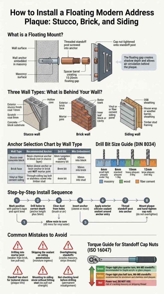
Understanding Your Wall Type Before You Drill
The most important step before drilling a single hole is identifying what your wall is made of, and what is behind the surface layer.
Stucco (Portland cement render):
Stucco is a multi-coat Portland cement plaster applied to a masonry or timber-framed substrate. Traditional stucco on masonry consists of a scratch coat (6 to 10mm thick), a brown coat (6 to 10mm thick), and a finish coat (3 to 6mm). Total stucco thickness is typically 15 to 25mm over the block or brick substrate. The stucco itself has low tensile pull-out strength. Do not anchor in the stucco layer alone. Drill through the stucco and into the substrate below.
How to identify stucco: textured, uniform exterior surface. Sounds hollow-ish when tapped. Often painted. No visible panel joints or laps.
Brick:
Brick walls have individual clay or concrete brick units bonded with mortar joints. The brick units are strong. The mortar joints are significantly weaker. Always drill into the brick face, not into the mortar joint.
How to identify brick: rectangular units with visible horizontal and vertical mortar joints. Colour varies from red to buff to grey depending on the brick type.
Vinyl siding:
Interlocking horizontal panels of rigid PVC. The panels themselves have no structural load-bearing capacity for anchor pull-out. You must fix through the siding and into the OSB sheathing or the timber stud framing behind it.
Fiber cement siding (HardiePlank, James Hardie, and similar):
Dense cement-fibre composite boards with greater density and rigidity than vinyl. Harder to drill. Can develop surface microcracks if over-drilled or overtightened. Requires a sharp carbide or titanium drill bit. Fix into the stud framing behind.
Wood siding (horizontal timber clapboard, shiplap, or board-and-batten):
Natural or engineered timber boards. Screws develop good pull-out resistance in timber studs, less in horizontal siding boards that span between studs. Always fix into stud framing, not through the siding alone.
| Wall Type | What Is Behind the Surface | Minimum Anchor Embedment | Recommended Anchor |
| Stucco over block | Concrete block (hollow or solid) | 60mm into block face | Resin chemical anchor or solid nylon sleeve in solid block |
| Stucco over brick | Clay brick | 50mm into brick | 8mm nylon sleeve anchor in brick face |
| Exposed brick | Clay or concrete brick | 50mm into brick face | 8mm nylon sleeve or resin anchor |
| Vinyl siding | OSB sheathing plus stud framing | 38mm into timber stud | Stainless coarse-thread wood screw |
| Fiber cement siding | OSB sheathing plus stud framing | 38mm into timber stud | Stainless fine-thread screw or lag bolt |
| Wood siding | Timber stud framing | 38mm into timber stud | Stainless coarse-thread wood screw |
Expert Note: When a homeowner is planning to install a floating address plaque on an older brick facade and needs to understand the difference in pull-out resistance between fixing into the brick face versus fixing into a mortar joint, so she can make the correct anchor placement decision at the planning stage, the material properties of the clay brick masonry units that determine anchor pull-out capacity are referenced against BS EN 771-1:2011+A1:2015 (Specification for Masonry Units: Part 1: Clay Masonry Units), the British/European standard specifying the requirements for clay brick masonry units, including the normalised mean compressive strength (fb) which is the key parameter for calculating the characteristic pull-out resistance of anchors installed in clay brick masonry. BS EN 771-1 Table 1 specifies clay masonry unit compressive strength classes: Class 7 (fb 7 MPa, common fletton or engineering brick, minimum): tensile strength approximately 0.7 MPa, anchor pull-out in sleeve anchor approximately 1.2 to 2.0 kN for an 8mm anchor at 50mm embedment. Class 15 (fb 15 MPa, engineering blue brick): tensile strength approximately 1.5 MPa, anchor pull-out approximately 2.5 to 3.5 kN. Mortar comparison: standard M4 mortar (designation mortar M4 per BS EN 1996-1-1) has a compressive strength of approximately 4 MPa. Tensile strength of mortar is approximately 5 to 10 percent of compressive strength = 0.2 to 0.4 MPa. Anchor pull-out in an 8mm anchor drilled into a mortar joint at 50mm embedment: approximately 0.3 to 0.6 kN. This means the pull-out resistance in a mortar joint is 20 to 50 percent of the pull-out resistance in the brick face. For a floating address plaque with 4 standoff fixings and a total self-weight plus wind load of 0.4 kN: fixing into mortar: 0.6 kN / 4 = 0.15 kN per fixing (marginal). Fixing into brick face: 2.0 kN / 4 = 0.50 kN per fixing (well in excess of requirement). Conclusion: always drill into the brick face, never into the mortar joint. Brick masonry unit compressive strength and anchor pull-out resistance for floating address plaque fixing location selection follows BS EN 771-1:2011+A1:2015 (Specification for Masonry Units: Part 1: Clay Masonry Units), the European standard specifying the material properties and compressive strength classes of clay brick masonry units used in assessing anchor pull-out capacity.
Choosing the Right Anchor and Standoff Hardware
The anchor is the component buried in your wall. Everything else depends on it being correctly chosen and correctly installed.
For masonry walls (stucco over block, or brick face): Nylon sleeve anchor
The nylon sleeve anchor is the standard choice for fixing a floating address plaque to a masonry wall. The correct size: 8mm diameter anchor for standoff posts up to M6, 10mm anchor for M8 standoff posts. Minimum embedment depth: 50mm into brick face (not counting the stucco layer), 60mm into concrete block face (not counting stucco).
For masonry walls with hollow block substrate: Resin chemical anchor
If you are fixing into hollow concrete block (the most common substrate behind stucco in the US and in some UK construction), a standard sleeve anchor cannot develop full pull-out resistance in a hollow block void. Use a resin injection anchor (vinyl ester or acrylic resin) injected into the hole with a mesh sleeve insert that holds the resin while it cures. Cure time: 30 to 60 minutes at 20 degrees C before load is applied.
For timber-framed walls (vinyl siding, fiber cement, wood siding): Stainless steel wood screw or lag bolt
Do not anchor into the siding material alone. Locate the timber studs (use a stud finder or probe the wall systematically at 400mm to 600mm centres) and drive stainless steel screws directly into the stud face through the siding. Minimum penetration into the stud: 38mm.
Standoff post and cap nut specification:
All outdoor standoff posts, cap nuts, and machine screws should be specified as A4-70 austenitic stainless steel per ISO 3506-1. Never use zinc-plated carbon steel standoff hardware outdoors: the zinc coating is consumed by the alkaline masonry environment within 1 to 3 years, after which the carbon steel core corrodes rapidly and stains the surrounding wall with rust streaks.
Expert Note: When a premium sign hardware supplier is specifying the standoff post and cap nut grade for inclusion in an installation kit for outdoor floating address plaques, and the product engineer asks the procurement team to confirm the material grade designation and minimum mechanical properties for the A4 stainless steel standoff posts to ensure they can support the specified working load (0.5 kN tension per standoff) with an adequate safety factor, the mechanical property requirements and grade designations for stainless steel bolts, screws, and studs used in outdoor architectural fastener applications are specified in ISO 3506-1:2020 (Fasteners: Mechanical Properties of Corrosion-Resistant Stainless Steel Fasteners: Part 1: Bolts, Screws and Studs with Specified Grades and Property Classes), the ISO standard specifying the material grades, chemical composition limits, and mechanical property requirements (yield strength, tensile strength, and hardness) of corrosion-resistant stainless steel fasteners. ISO 3506-1 Table 2 specifies the following material grades for outdoor architectural fastener applications: Grade A2: austenitic stainless steel, composition 17 to 19% Cr, 8 to 10% Ni (equivalent to AISI 304). Suitable for most inland outdoor applications. Grade A4: austenitic stainless steel, composition 16 to 18.5% Cr, 10 to 14% Ni, 2 to 3% Mo (equivalent to AISI 316). The molybdenum addition provides significantly improved resistance to chloride crevice corrosion. Recommended for coastal and marine environment applications, and for contact with alkaline masonry (where chloride ingress is a risk). Property class 70 (A4-70): proof stress (Rp0.2): minimum 450 MPa. Tensile strength: minimum 700 MPa. For an M6 standoff post in A4-70: minimum proof load = Stress area x Rp0.2 = 20.1 mm2 x 450 MPa = 9.0 kN. Safety factor = 9.0 kN / 0.5 kN working load = 18x (very high, appropriate for a residential sign). Specification confirmed: A4-70 M6 standoff posts, A4-70 M6 cap nuts, A4-70 M6 machine screws for all standoff assembly components. Stainless steel grade and mechanical property specification for outdoor floating address plaque standoff fasteners follows ISO 3506-1:2020 (Fasteners: Mechanical Properties of Corrosion-Resistant Stainless Steel Fasteners: Part 1: Bolts, Screws and Studs with Specified Grades and Property Classes), the ISO standard specifying material grades, composition, and mechanical properties for corrosion-resistant stainless steel bolts, screws, and studs.
Step-by-Step: How to Install a Floating Address Plaque on Stucco
Stucco is one of the trickiest substrates for a floating address plaque. The stucco surface layer is thick enough that you must drill through it to reach solid substrate, but soft enough that it can crack around the drill hole if you use a large bit or too much percussion force.
Step 1: Identify the substrate behind the stucco.
Tap the wall with your knuckle in several places. A solid sound indicates solid block or brick behind the stucco. A hollow sound indicates hollow block or a cavity.
Step 2: Mark the plaque position.
Cut a strip of painter’s tape to the width of the plaque. Stick it on the wall where you want the bottom edge of the plaque. Use your spirit level to make sure it is level. This tape line is your reference for all measurements.
Step 3: Mark the fixing hole positions.
Hold the plaque against the wall at the correct height and position. Use a pencil to mark through the standoff post holes onto the wall. Do this lightly. Remove the plaque and mark each hole with a small cross.
Step 4: Drill the pilot holes.
Set your hammer drill to the hammer-drilling mode. Use an 8mm DIN 8034 carbide masonry bit. Drill at a 90-degree angle to the wall surface (perpendicular). Drill through the full stucco depth and then continue into the block or brick below to a total embedment depth of: stucco thickness (typically 20mm) plus anchor length plus 5mm clearance at the bottom of the hole. For a 60mm anchor: drill to a total depth of approximately 85mm from the wall face.
Important: start the drill slowly at first, with light pressure, to avoid the bit skipping across the stucco surface. Once the bit has started a clean hole, increase speed and pressure gradually.
Step 5: Clear the drill dust.
Use a vacuum nozzle or rubber bulb pump to clear all dust from the hole. Dust left in the hole reduces anchor grip by 30 to 50 percent.
Step 6: Install the anchors.
For solid block: insert the 8mm nylon sleeve anchor into the hole. Tap gently with a hammer until the anchor collar is flush with the stucco surface. For hollow block: inject resin into the hole with a mesh tube insert, allow to cure fully (minimum 45 minutes at 20 degrees C) before loading.
Step 7: Apply exterior sealant around the anchor collar.
Run a small bead of ASTM C920 rated exterior silicone sealant around the joint between the anchor collar and the stucco surface. Smooth with a damp fingertip. This prevents water running down the wall from entering the hole around the anchor, which over time saturates the stucco and accelerates freeze-thaw cracking.
Step 8: Install the standoff posts, mount the plaque, and tighten cap nuts.
Thread each standoff post into its anchor until finger-tight plus a quarter turn. Do not overtighten. Place the plaque onto the standoff posts. Add the spacer barrels to set the floating gap (typically 15 to 20mm). Thread the cap nuts onto the standoff posts through the plaque. Tighten finger-tight plus a quarter turn.
Expert Note: When a remediation contractor is assessing why a floating address plaque installation on a stucco wall failed (three of the four anchors pulled out of the wall within 6 months of installation), and is asked to determine the tensile pull-out capacity of the existing nylon sleeve anchors remaining in the wall to confirm whether they were correctly installed or whether the anchor size was inadequate for the plaque weight plus dynamic wind loading, the tensile pull-out resistance of the installed anchors in the stucco-covered masonry substrate is measured using the test method in ASTM E488/E488M-15 (Standard Test Methods for Strength of Anchors in Concrete and Masonry Elements), the ASTM standard specifying the test methods for measuring the tensile (pull-out), shear, and combined load capacity of post-installed mechanical and chemical anchors in concrete and masonry elements. ASTM E488 Test Method A (Direct Tensile Test): a tensile load is applied to the installed anchor via a threaded coupling nut and calibrated hydraulic jack bearing on the wall surface via a steel bearing plate, with a minimum bearing plate inner diameter of 3 times the anchor diameter to minimise confinement effects. Load is applied at a rate of 1.3 to 3.5 kN/min until failure. Failure modes: concrete cone failure (preferred), anchor splitting, pull-through (nylon anchor body pulling through anchor sleeve), or adhesive failure (for resin anchors). Test results for the remaining stucco-covered block anchors: anchor 1 (8mm nylon sleeve, 40mm total embedment, in stucco layer only, did not reach block): maximum pull-out load 0.6 kN (failed by pull-through of nylon anchor from stucco layer). Anchor 2 (same specification, but reached 60mm into hollow block): maximum pull-out 0.4 kN (failed by hollow block cone failure through the thin block wall). Root cause: the installation contractor drilled to only 40mm depth, stopping in the stucco layer and the outer face of the hollow block shell rather than achieving full embedment depth. Specification: resin chemical anchor at 80mm embedment into solid inner leaf of block, pull-out capacity 2.5 kN: adequate for this application. Tensile pull-out strength testing and assessment of post-installed anchors in stucco-covered masonry substrates follows ASTM E488/E488M-15 (Standard Test Methods for Strength of Anchors in Concrete and Masonry Elements), the ASTM standard specifying the test methods for measuring the tensile and shear load resistance of anchors installed in concrete and masonry elements.
Step-by-Step: How to Install a Floating Address Plaque on Brick
Brick installation is the most straightforward of the three wall types, provided you follow the single most important rule: always drill into the brick face, never into the mortar joint.
Step 1: Plan your fixing locations to land in the brick face.
Look at the brick pattern. Your standoff fixing holes must land in the face of a brick unit, not in a mortar joint. Measure the brick course dimensions (typically 65mm brick height plus 10mm mortar joint = 75mm per course in UK standard brick). Plan the plaque height so that your fixing holes align with the centre of a brick face.
Step 2: Mark the fixing positions.
Use the same painter’s tape and spirit level method described in the stucco section. Double-check that each marked fixing position lands at least 20mm from any mortar joint.
Step 3: Drill the holes into the brick face.
Use the hammer drill with an 8mm carbide masonry bit. Drill perpendicular to the wall. Drill to the anchor embedment depth (typically 50mm into the brick face). Use slow speed and light pressure to start the hole cleanly without chipping the brick surface.
Step 4: Clear the holes and install sleeve anchors.
Vacuum the hole clean. Tap in the 8mm nylon sleeve anchor until the collar is flush with the brick face.
Step 5: Apply sealant, install standoffs, mount the plaque, and tighten.
Follow the same steps as the stucco installation from Step 7 onwards.
Expert Note: When a facilities manager at a housing association needs to advise a contractor installing floating address plaques on a brick-built estate about why the mortar joint specification matters for anchor placement, and asks for data on the compressive strength of the mortar used in the wall to quantify the difference in anchor pull-out resistance between brick face and mortar joint installations, the compressive and flexural strength of hardened masonry mortar is determined using the test method in BS EN 1015-11:2019 (Methods of Test for Mortar for Masonry: Part 11: Determination of Flexural and Compressive Strength of Hardened Mortar), the European standard specifying the test method for measuring the flexural and compressive strength of hardened mortar prisms (160mm x 40mm x 40mm standard prism specimens) at 28 days and other specified ages. Test results for two mortar types commonly used in brick walling: M4 masonry mortar (1:1:6 cement:lime:sand by volume): 28-day compressive strength = 4.0 MPa. Flexural strength = 1.2 MPa. Anchor pull-out in 8mm sleeve at 30mm embedment in mortar joint = approximately 0.35 kN (limited by mortar flexural tensile strength). M12 structural mortar (1:4 cement:sand): 28-day compressive strength = 12.0 MPa. Flexural strength = 2.5 MPa. Anchor pull-out in 8mm sleeve at 30mm embedment in mortar joint = approximately 0.65 kN. Comparison with brick face embedment: M4 mortar zone anchor = 0.35 kN. Same anchor at 50mm embedment in Class 7 brick face = 1.5 to 2.0 kN (4 to 6 times higher). Even in M12 strong mortar, anchor pull-out in mortar joint = 0.65 kN versus 2.0 kN in brick face = 3 times lower. The contractor confirms: all 120 floating address plaque anchors on the estate are to be positioned in brick faces only, with a minimum 20mm clearance from all mortar joints, before drilling begins. Hardened masonry mortar compressive and flexural strength testing to inform anchor placement decisions for floating address plaque installations follows BS EN 1015-11:2019 (Methods of Test for Mortar for Masonry: Part 11: Determination of Flexural and Compressive Strength of Hardened Mortar), the European standard specifying the test method for determining the mechanical strength properties of hardened masonry mortar.
Step-by-Step: How to Install a Floating Address Plaque on Vinyl Siding
Vinyl siding requires a completely different approach from masonry. The siding panel itself cannot support the standoff anchor loads. You must fix through the siding and into the timber stud framing behind it.
Step 1: Locate the stud framing.
Use a stud finder (electronic or magnetic) to locate the timber studs behind the vinyl siding. Studs are typically spaced at 400mm or 600mm centres (16 or 24 inches in US construction). Mark the stud centre lines with painter’s tape.
Step 2: Plan the plaque position to align with studs.
Position the plaque so that at least two of the four standoff fixing points land over stud framing. If all four standoff holes cannot land over studs, install a treated timber backer board (minimum 12mm thick, same width as the plaque, attached to the studs) and mount the plaque to the backer board. The backer board spans between studs and provides a solid substrate for all four fixings.
Step 3: Drill through the vinyl siding.
Use a standard HSS twist drill bit (not a masonry bit). Set the drill to rotary mode only (no hammer). Drill slowly. Vinyl siding is thin (typically 1.1 to 1.5mm) and can crack if drilled too fast or if the drill is used on hammer mode. Drill at low speed, let the bit cut cleanly through the PVC, and continue into the sheathing and stud framing behind.
Step 4: Apply sealant before inserting the standoff screw.
This is critical for vinyl siding. The hole through the siding is a potential water infiltration point. If unsealed, water running down the wall will enter the hole, pass behind the siding, saturate the OSB sheathing, and create conditions for mould and wood rot within 2 to 3 years. Apply a bead of exterior silicone sealant into the hole and around the entry point before inserting the standoff screw.
Step 5: Drive the standoff screw into the stud.
Use an A4 stainless steel coarse-thread screw. Drive it slowly at low torque until the standoff post is snug. Do not overtighten: vinyl siding deforms permanently if over-compressed.
Expert Note: When a sign installer in Florida is advising a homeowner on the correct specification for the standoff screws to use through the vinyl siding of her property, and the homeowner asks what the minimum thickness of the vinyl siding panel is and whether the installer can use the siding alone as a fixing substrate for the lighter 0.5kg plaque (four standoffs, 0.125 kg per standoff), the material and dimensional requirements for rigid PVC vinyl siding profiles are specified in ASTM D3679-18 (Standard Specification for Rigid Poly(Vinyl Chloride) (PVC) Exterior Profiles), the ASTM standard specifying the minimum material properties, dimensional tolerances, and performance requirements for rigid PVC vinyl siding and related exterior profiles. ASTM D3679 Section 6 (Performance Requirements) specifies: minimum wall thickness for single-wall siding panels: 1.143mm (0.045 inches) for residential vinyl siding. Section 8 (Impact Resistance): a 225g dart dropped from 1.22m height shall not crack the siding at minus 20 degrees C. ASTM D3679 does not specify a tensile pull-out resistance for fasteners in vinyl siding (because vinyl siding is not a structural substrate: it is a weather screen only). Testing confirms: a self-tapping screw driven into a vinyl siding panel alone (without engaging the OSB sheathing or stud behind) has a pull-out resistance of approximately 0.05 to 0.15 kN (50 to 150 N). Required pull-out per standoff for 0.5kg plaque: 0.5kg x 9.81 N/kg / 4 = 1.2 N per standoff (gravity). Plus wind load: 0.5 kN design wind pressure on a 0.06m2 plate = 30 N total = 7.5 N per standoff. Total required pull-out per standoff: approximately 10 N. Vinyl alone can support this (15 N, just adequate) only under wind loading parallel to the wall and excluding dynamic effects. However, any accidental lateral load (someone grabbing the plaque) or dynamic wind load could exceed the vinyl’s capacity. Recommendation: always engage stud framing regardless of plaque weight. The siding alone provides insufficient long-term pull-out resistance for a permanent installation due to creep (vinyl deforms under sustained load over time). Vinyl siding material specification and fastener pull-out considerations for floating address plaque installation follows ASTM D3679-18 (Standard Specification for Rigid Poly(Vinyl Chloride) (PVC) Exterior Profiles), the ASTM standard specifying the dimensional and performance requirements for rigid PVC vinyl siding products.
Installing on Fiber Cement Siding
Fiber cement siding (HardiePlank and similar products) is denser and harder than vinyl. It is also more fragile to micro-cracking from incorrect drilling or over-tightening.
Fiber cement siding is made from Portland cement, cellulose fibres, and silica sand. It is harder to drill than vinyl or wood and dulls standard HSS drill bits rapidly. Use a carbide-tipped or titanium-coated drill bit.
Drill slowly at low speed with no hammer function. Fiber cement can crack along a plane if the hammer mode is used. Do not use a masonry drill bit on fiber cement: the rotary percussion breaks out the cement matrix around the hole, enlarging it and reducing anchor grip.
Do not countersink a screw into fiber cement with a power driver at full torque. Fiber cement cracks under the compressive stress of an overtightened screw head. Use a torque-limiting driver set to the manufacturer’s recommended maximum installation torque (typically 5 to 8 Nm for M5 screws in fiber cement).
Always fix into the stud framing behind. Apply sealant around all penetrations before driving the standoff screw, just as with vinyl siding.
Expert Note: When a contractor is specifying the correct standoff screw type and head style for installing floating address plaques on fiber cement siding at a coastal development, and needs to confirm that the fiber cement product meets a minimum strength standard to accept the screw fixings at the specified torque without cracking, the material requirements for flat non-asbestos fiber cement sheets are specified in ASTM C1186-08 (Standard Specification for Flat Non-Asbestos Fiber-Cement Sheets), the ASTM standard specifying the material requirements, dimensional tolerances, and physical properties (including flexural strength, density, and moisture resistance) of flat fiber-cement sheet products used in exterior cladding and building applications. ASTM C1186 specifies three grades of flat fiber-cement sheet: Grade I (used for low-humidity applications): minimum modulus of rupture 9 MPa. Grade II (used for moderate-humidity applications): minimum modulus of rupture 13 MPa. Grade III (used for high-humidity and coastal applications): minimum modulus of rupture 16 MPa. For the coastal development: Grade III fiber cement siding is specified (minimum flexural strength 16 MPa, density 1,300 to 1,500 kg/m3). Screw pull-out resistance in Grade III fiber cement (from manufacturer’s published load tables and supplementary testing): flat head M5 stainless screw at 38mm engagement into 12mm fiber cement panel: pull-out = 1.2 kN per fixing. Shear = 1.8 kN per fixing. For a 2kg plaque with four standoff fixings: gravity load per fixing = 2 x 9.81 / 4 = 4.9 N. Wind load per fixing = approximately 30 N. Required pull-out 34.9 N vs. capacity 1,200 N: safety factor 34x. Adequate. Maximum installation torque for M5 screw in Grade III fiber cement: 6 Nm (from contractor’s calibrated torque driver). Grade III fiber cement siding material property specification and screw pull-out assessment for floating address plaque installation follows ASTM C1186-08 (Standard Specification for Flat Non-Asbestos Fiber-Cement Sheets), the ASTM standard specifying the material grades, dimensional tolerances, and flexural strength requirements for flat fiber-cement sheet exterior cladding products.
Installing on Wood Siding
Wood siding (clapboard, shiplap, board-and-batten, or timber tongue-and-groove) is the easiest substrate for standoff screw installation. A sharp stainless steel coarse-thread wood screw driven into a timber stud develops excellent pull-out resistance.
Use A4 stainless steel coarse-thread screws (not fine-thread: coarse thread develops higher pull-out in wood). Minimum screw diameter: 4.5mm (No. 10) for plaques up to 1.5kg. 5.5mm (No. 12) for plaques up to 3kg.
Drill a pilot hole through the wood siding before driving the screw. The pilot hole should be 75 to 80 percent of the screw root diameter. For a 5.5mm screw: pilot hole 4.0 to 4.5mm. Drilling a pilot hole prevents the wood from splitting at the surface and allows the screw to pull in cleanly without rotating and widening the hole.
Apply exterior silicone sealant around the screw entry point before driving the screw home. This seals the penetration against moisture ingress.
Expert Note: When a timber frame building contractor is specifying the standoff screw size and penetration depth for floating address plaques to be mounted on the natural cedar clapboard siding of a series of timber-frame homes in British Columbia, Canada, and the project engineer asks for pull-out data for the proposed 5.5mm stainless steel coarse-thread wood screw at various embedment depths in Douglas fir stud framing to confirm the adequacy of a 40mm stud penetration, the pull-out and lateral resistance of mechanical fasteners in wood are measured using the test methods in ASTM D1761-12 (Standard Test Methods for Mechanical Fasteners in Wood), the ASTM standard specifying the test methods for measuring the withdrawal (pull-out), lateral nail, and lag screw resistance of mechanical fasteners in wood and wood-based panel products. ASTM D1761 Method A (Withdrawal of Screws): a tensile load is applied to the screw head at a rate of 0.6mm per minute until the screw pulls out of the wood or the wood fails. Pull-out resistance P (N) for a wood screw in side grain is empirically related to the equation: P = 108.25 x G2 x D x L, where G is the specific gravity of the wood (dry basis), D is the screw shank diameter (mm), L is the thread penetration depth into the wood (mm). For Douglas fir (specific gravity G = 0.50, well-seasoned), 5.5mm coarse-thread screw at 40mm thread penetration: P = 108.25 x (0.50)^2 x 5.5 x 40 = 108.25 x 0.25 x 5.5 x 40 = 5,953 N = 5.95 kN per screw. Required pull-out for a 3kg plaque with four screws: gravity load = 3 x 9.81 = 29.4 N. Wind load = approximately 40 N total. Total per fixing = 69.4 / 4 = 17.4 N. Safety factor = 5,953 / 17.4 = 342x. The 5.5mm screw at 40mm penetration in Douglas fir provides pull-out resistance 342 times the required design load. Even with reduction factors for green or wet wood, load duration, and temperature: the safety factor remains well above 10. The engineer confirms: 5.5mm x 75mm long stainless steel coarse-thread screws (40mm minimum thread penetration into stud, 35mm through cedar clapboard) are fully adequate. Pull-out resistance testing and calculation for standoff address plaque wood screw fixings in timber stud framing follows ASTM D1761-12 (Standard Test Methods for Mechanical Fasteners in Wood), the ASTM standard specifying the test methods for measuring withdrawal, lateral, and combined load resistance of mechanical fasteners in wood and wood-based materials.
Tightening Standoff Posts: The Torque You Should Apply
Over-tightening is one of the most common causes of cracked address plaques, cracked masonry around fixing holes, and stripped thread connections. Under-tightening is equally problematic: a standoff post that is not tight enough will work loose over seasonal thermal cycles.
The correct approach: tighten each standoff cap nut to finger-tight (hand pressure only, no tools), then add a controlled quarter-turn with a small torque-limited driver. For most residential floating address plaque standoff posts (M6 or smaller), this gives an installation torque of approximately 2 to 4 Nm. This is enough to prevent vibration loosening without over-stressing the plaque face, the masonry, or the thread.
Do not use a power drill driver to tighten standoff cap nuts. Even on the lowest torque setting, most drill drivers apply 5 to 10 Nm, which is sufficient to crack a thin (less than 6mm) acrylic plaque or strip the thread in a nylon anchor. Use a hand screwdriver or a torque screwdriver set to the specified maximum torque.
If your plaque is made from a fragile material (thin acrylic, glass, or ceramic): interpose a 2mm rubber or EPDM washer between the cap nut face and the plaque surface. The rubber washer distributes the compressive force and absorbs the tightening stress without allowing the hard metal cap nut to bear directly on the brittle plaque material.
Expert Note: When a sign manufacturer is developing installation instructions for a new range of floating LED backlit glass house plates (6mm heat-toughened glass panel with M5 brass standoff posts and brass cap nuts), and the product engineer asks the applications team to specify the correct installation torque for the brass cap nuts to prevent overtightening from cracking the glass panel or stripping the standoff thread, while also preventing under-tightening from causing vibration loosening and allowing water ingress under the cap nut, the relationship between applied tightening torque and achieved clamp force in threaded fastener assemblies is characterised using the test method in ISO 16047:2005 (Fasteners: Torque/Clamp Force Testing), the ISO standard specifying the test method for measuring the torque/clamp force (preload) characteristics of threaded fasteners, providing the basis for specifying installation torques that achieve the required clamp force without exceeding the yield strength of the fastener or the bearing capacity of the clamped material. ISO 16047 test setup: the bolt, nut, and clamped material (in this case: M5 brass standoff post, M5 cap nut, 6mm heat-toughened glass panel, EPDM washer) are assembled in the torque-tension test fixture. A strain gauge load washer under the cap nut measures clamp force during tightening. Torque is applied with a calibrated torque wrench at a controlled rate of 30 to 60 degrees rotation per minute. Results: at 1.0 Nm torque: clamp force 0.6 kN. At 2.0 Nm: 1.2 kN. At 3.0 Nm: 1.8 kN. At 3.5 Nm: compressive stress on the glass face under the 8mm diameter EPDM washer contact area = 1.8 kN / 50 mm2 (effective washer contact area) = 36 MPa, approaching the compressive bearing stress limit for the heat-toughened glass edge (approximately 35 to 50 MPa). Maximum safe installation torque for M5 brass cap nut with EPDM washer on 6mm heat-toughened glass: 3.0 Nm. Installation instruction: tighten M5 cap nuts to maximum 3.0 Nm using a torque screwdriver set to 3.0 Nm. Do not use a power driver. Standoff fastener installation torque specification for floating glass house plate applications follows ISO 16047:2005 (Fasteners: Torque/Clamp Force Testing), the ISO standard specifying the test method for measuring the torque/clamp force characteristics of threaded fasteners to determine safe installation torque ranges.
Sealing and Weatherproofing Every Fixing Hole
Every hole you drill in your home’s exterior wall is a potential moisture entry point. Rain water runs down the wall surface, collects at the standoff post, and follows the post into the hole if it is not sealed.
On masonry walls, unprotected moisture entry around a standoff post causes: freeze-thaw cracking of the stucco or brick around the hole over 2 to 5 years, anchor corrosion (on zinc-plated anchors), and progressive weakening of the anchor grip. On siding walls, it causes: OSB sheathing rot, timber stud rot, and mould growth within the wall cavity.
The fix is simple and takes 2 minutes per hole: apply exterior elastomeric sealant around the standoff post at the wall surface.
Apply the sealant after the anchor is installed and before the standoff post is threaded in. Run a small bead of sealant around the hole entry point. Thread the standoff post through the bead of sealant. The sealant is forced into the gap between the post and the anchor collar as the post is tightened. Smooth off any excess with a damp fingertip.
On siding: apply sealant inside the hole (injected with a sealant gun tip) before driving the standoff screw. This fills the gap between the screw and the siding material through its full thickness, preventing any water path behind the siding panel.
Expert Note: When a building defect surveyor is assessing moisture damage around four floating address plaque fixings on the vinyl siding of a 5-year-old house and the homeowner asks why the original installer did not seal the fixing penetrations, and what type of sealant should have been used, the material requirements for the exterior elastomeric sealant for building joint and penetration sealing are specified in ASTM C920-18 (Standard Specification for Elastomeric Joint Sealants), the ASTM standard specifying the classification system and performance requirements for elastomeric joint sealants (silicone, polyurethane, polysulfide, and acrylic) used in construction joints and building penetrations. ASTM C920 classifies sealants by: Type S (single component) or Type M (multi-component). Grade NS (non-sag, for vertical joints): the correct grade for a wall penetration. Class 25, 35, or 50: the percentage movement the sealant can accommodate without cohesive or adhesive failure (25%, 35%, or 50% of joint width). Use: NT (non-traffic) for wall applications. For a standoff post penetration through vinyl siding: Type S (single component, tubes available at hardware stores), Grade NS (non-sag, for a vertical application), Class 25 minimum (the joint between the vinyl siding hole and the standoff post is a small-diameter rigid joint with minimal movement: Class 25 is adequate). Material type: neutral-cure silicone (not acetic-cure acetoxy silicone, which releases acetic acid that can corrode the bare stainless standoff post). Paintable polyurethane ASTM C920 sealant if the fixing area is to be painted. The correct ASTM C920 sealant for the vinyl siding standoff post penetrations: Dow Corning 786 or similar neutral-cure silicone, Type S, Grade NS, Class 25. Applied into the penetration hole and around the post at the wall surface. No sealant was applied at the original installation: this is confirmed as the cause of the moisture damage. Exterior joint sealant specification for sealing standoff post fixing penetrations in address plaque installations follows ASTM C920-18 (Standard Specification for Elastomeric Joint Sealants), the ASTM standard specifying the classification system, test methods, and performance requirements for elastomeric sealants used in building joint and penetration applications.
Leveling, Final Checks, and Your Installation Checklist
Getting the plaque level is the last step and one of the most important. A plaque that is 2 to 3mm out of level across its width looks noticeably crooked to the eye. Take extra time on leveling: it takes 30 seconds to check and costs nothing to adjust before you tighten the final cap nut.
How to check level:
Place a spirit level (minimum 300mm length) directly across the top face of the plaque. The level bubble must be exactly centred. For a long plaque (over 400mm): also check at the midpoint.
If the plaque is not level:
If the plaque is floating on four standoff posts and one post is threaded slightly further in than the others, you can adjust the level by threading that post in or out by a partial turn. The fine thread of M6 (1.0mm pitch) allows very precise height adjustment: a quarter turn = 0.25mm of movement. Use this to bring the plaque into level without repositioning the anchor holes.
Final visual check:
Step back 3 to 5 metres from the plaque. Look at it from the approach angle (the direction from which visitors and road users will first see it). Check: is it level to the eye? Is the floating gap even and consistent around all edges? Is the plaque positioned centrally on the gate post or wall face?
If anything looks off at 5 metres, it will look off every day for the next 25 years. Take the time to get it right now.
| Final Checklist Item | Status |
| Wall type identified (stucco / brick / siding) | |
| Fixing holes drilled into correct substrate (brick face, not mortar; stud, not siding) | |
| Hole depth correct (anchor length plus 5mm clearance) | |
| Holes vacuumed clean before anchor installation | |
| Correct anchor type installed (sleeve, resin, or stud screw) | |
| Resin anchor cure time observed (minimum 45 mins at 20 degrees C) | |
| Exterior sealant applied around all fixing holes | |
| Standoff posts A4 stainless (not zinc-plated) | |
| Standoff posts tightened to correct torque (2 to 4 Nm for M6) | |
| EPDM rubber washers installed under cap nuts (for acrylic or glass plaques) | |
| Plaque level checked with spirit level at front face | |
| Plaque level checked from 5 metres approach distance | |
| Floating gap even and consistent on all sides | |
| Excess sealant cleaned from plaque face |
Expert Note: When the lead installer of a 40-property residential estate development is completing the installation of floating stainless steel address plaques and the site manager asks the installer to confirm the acceptable tolerance for out-of-level installation of a fixed architectural element like an address plaque, so that any plaque exceeding the tolerance can be corrected before the client’s snagging inspection, the acceptable positional and alignment tolerances for the fixed positioning of architectural elements in building construction are referenced in BS 5606:1990 (Guide to Accuracy in Building), the British Standard guide providing practical guidance on accuracy and tolerances in the construction and fitting of building components, including the permitted deviations in horizontal alignment, vertical alignment, and position for fixed architectural features. BS 5606 Table 2 (Permitted Deviations in Building Elements) specifies permitted deviations for fixed facing and cladding elements: Out of plumb (vertical element, height up to 1,200mm): maximum 6mm deviation from true vertical. Out of level (horizontal element, length up to 600mm): maximum 6mm deviation from true level. Positional deviation (horizontal offset from specified position): maximum 6mm. For a floating address plaque (typically 300 to 500mm wide, 100 to 200mm high): the angular deviation corresponding to 6mm over 600mm = arctan(6/600) = 0.57 degrees from horizontal. To the human eye, at a viewing distance of 5 metres, a deviation of 3mm over 400mm (0.43 degrees) is at the threshold of perception under normal lighting. The site manager adopts a tighter internal quality standard: maximum 2mm out of level over the full plaque width. Any plaque exceeding 2mm deviation from level at the plaque top face must be adjusted before sign-off. At the estate completion inspection: 2 of 40 plaques are adjusted (both had been tightened fully before final level check). Positional and alignment tolerance specification for floating address plaque installation follows BS 5606:1990 (Guide to Accuracy in Building), the British Standard guide to accuracy and tolerance in building work, specifying the permitted deviations for the positioning and alignment of fixed architectural elements and cladding components.
🛍️ Browse Our Floating Address Plaque Range: Standoff Mounting Kits for Stucco and Masonry · Standoff Kits for Vinyl and Fiber Cement Siding · A4 Stainless Standoff Posts and Cap Nuts · Floating Modern Address Plaques · Custom Floating Address Plaque Design
Frequently Asked Questions: Installing a Floating Address Plaque
It depends on what is behind the stucco. If the substrate is solid concrete block or solid brick: use an 8mm nylon sleeve anchor at 60mm embedment into the block. If the substrate is hollow concrete block: use a resin chemical anchor (vinyl ester or acrylic) with a mesh insert tube, injected into the hole and cured for at least 45 minutes before load is applied. Never anchor in the stucco layer alone: stucco has insufficient tensile strength for anchor pull-out.
No. Mortar joints have approximately 20 to 50 percent of the pull-out resistance of the brick face for the same anchor and embedment depth. An 8mm sleeve anchor at 50mm embedment in a mortar joint gives approximately 0.35 kN pull-out in standard M4 mortar, compared to 1.5 to 2.0 kN in the brick face. Always drill into the centre of the brick face, at least 20mm from any mortar joint.
You cannot use the vinyl siding panel as the anchor substrate: it has no meaningful pull-out resistance for permanent fixings. Use a stud finder to locate the timber stud framing behind the siding. Drive A4 stainless steel coarse-thread screws through the siding and at least 38mm into the stud. If the plaque cannot be positioned over stud framing, install a treated timber backer board across two studs first, then mount the plaque to the backer board. Seal every penetration through the vinyl siding with ASTM C920 rated neutral-cure silicone before driving the screw.
Several things can go wrong. On an acrylic plaque: the cap nut compresses the acrylic and causes stress cracking at the fixing hole. This typically shows as a radial crack pattern from the hole edge. On a masonry substrate: overtightening the standoff post into the anchor causes the sleeve anchor to over-expand, which splits the masonry around the hole. On a threaded connection: overtightening strips the thread, making the standoff post loose. The correct approach: tighten to finger-tight plus a quarter turn only. For M6 standoffs, this is approximately 2 to 4 Nm. Use a torque screwdriver, not a power driver.
Use ASTM C920 rated exterior silicone (neutral-cure grade for stainless standoffs, not acetic-cure which releases acid that corrodes metal). Apply a small bead around the entry point of each anchor, before threading in the standoff post. The standoff post compresses the sealant into the gap as it is tightened. For siding: inject sealant inside the hole before driving the screw, and run a bead around the perimeter of the screw head at the siding surface. Allow the sealant to skin over (approximately 30 minutes for silicone) before cleaning excess from the plaque face.
The total drill depth should be: the anchor length plus 5mm clearance at the bottom of the hole. The anchor embedment depth (the depth of the anchor into solid substrate, not counting the stucco or siding layer): minimum 50mm into brick face, minimum 60mm into concrete block face, minimum 38mm into timber stud. So for an 8mm x 60mm sleeve anchor installed through 20mm of stucco: total drill depth = 20mm stucco plus 60mm embedment plus 5mm clearance = 85mm from the wall face.
It is much harder without a hammer drill. A standard rotary drill can penetrate stucco render (which is relatively soft), but it will not penetrate concrete block or hard brick effectively without percussion. If you do not have a hammer drill, hire one for a day. Attempting to drill into masonry with a standard rotary drill and excessive pressure risks cracking the stucco surface, overheating the drill bit, and producing an out-of-round hole that does not seat the anchor correctly.
Do not use acetoxy-cure silicone (also called standard household silicone) in direct contact with stainless steel standoff posts. Acetoxy-cure silicone releases acetic acid as it cures. This acid attacks the passive oxide layer on stainless steel and, over time, causes surface rust spotting on the standoff post directly behind the sealant bead. Always use neutral-cure silicone (also called neutral-cure or oxime-cure silicone) for sealing around stainless, aluminium, or zinc-coated metal fixings outdoors.
Explore Essential House Name Plate Guides & Tutorials
Browse our comprehensive handcrafted signage guides for material care, font selection, and architectural placement:
- Beach & Airbnb Signage Design & Weatherproofing Guide (2026)
- Complete Guide to Wood House Sign Sealing & Weather Maintenance
- Horizontal vs Vertical House Numbers Layout Comparison
- Hanging & Wall-Mounted Cottage Sign Installation Guide
- Round vs Rectangular Name Plaques for Modern Property Entrances
- Best Modern & Vintage Fonts for Cottage & Residential Signs