A backlit LED house number done correctly looks like it grew out of the wall no visible wire, no surface conduit, no mounting screws. Done incorrectly, it looks like a DIY project that ran out of patience, detracting from the professional finish of your illuminated house signs. The difference between those two outcomes is almost entirely in the planning phase, before a single hole is drilled. This guide covers every step in professional-grade detail: wall assessment, hidden wire routing, standoff mounting, wiring, weatherproofing, and alignment.
📥 Download the Free Installation Checklist: Our Backlit LED House Number Installation Checklist covers every step print it before you pick up a drill.
What Tools and Materials Do You Need Before Installing Backlit LED House Numbers?
Gathering every item before starting eliminates the most common installation error: making irreversible decisions (drilling, cutting) before discovering a missing component. Here is the complete professional toolkit:
Electrical & Wiring
- 12V DC LED driver (Class 2, UL-listed): Sized to total LED wattage × 1.25 safety margin
- Low-voltage 2-core wire: 18 AWG minimum for runs up to 10m; 16 AWG for runs 10–20m
- Waterproof wire connectors (IP68-rated): Silicone-filled lever connectors — not standard wire nuts
- NEMA 3R outdoor-rated enclosure: For housing the LED driver in an external location
- Heat-shrink tubing: 3:1 shrink ratio, adhesive-lined, for all junction insulation
Drilling & Mounting
- Hammer drill with SDS-plus chuck: For masonry penetrations
- Diamond-tipped core drill bit (20–25mm diameter): For clean wire-channel holes through brick/render
- Standard twist drill set (3mm, 4mm, 6mm, 8mm): For pilot holes and standoff anchors
- Right-angle drill attachment: For drilling in recessed porticos or tight corners
- Fish tape (fiberglass, 25ft minimum): For threading wire through wall cavities
- Countersink bit: For flush standoff mounting on flat substrates
Measurement & Alignment
- Magnetic level with dual bubble vials (horizontal + vertical): For plumb and level alignment
- Tape measure: For centre-point calculations and standoff spacing
- Paper template: Manufacturer-supplied; tape into position before drilling
- Pencil or chalk marker: For transferring template points to wall
Sealing & Finishing
- Neutral-cure silicone sealant (transparent): For sealing all wall penetrations
- Isopropyl alcohol (90%+): For cleaning wall surface before adhesive bonding
- Touch-up paint (matching wall colour): For any minor surface marks from template tape
Expert Note: When routing low-voltage wiring through a masonry wall for backlit LED house numbers, a fiberglass fish tape with 25-foot flexible rod and offset hook tip is used to thread the 18 AWG 2-conductor low-voltage wire (meeting ASTM B3 soft-annealed copper conductor specification) through a drilled wall channel. Fish tape selection and minimum conductor gauge for Class 2 low-voltage circuits are specified in NEC Article 725.130, which governs wiring methods for Class 2 and Class 3 remote-control and signalling circuits.
How Do You Choose the Right Backlit LED Number Kit for Your Wall Type?
The wrong kit for the wall type results in structural compromise, visible damage, or an impossible hidden-wire route. Here is the selection matrix:
| Wall Type | Mounting Method | Drill Bit Required | Wire Routing Method | Kit Compatibility |
| Brick (solid) | M6 masonry anchors | SDS carbide + diamond core | Through-wall drilled channel | Any standard backlit kit |
| Render / Stucco over block | M6 nylon sleeve anchors | 6mm masonry bit | Through-wall channel or surface conduit | Any standard kit |
| Timber cladding / weatherboard | 6mm wood screw | 5mm wood bit | Through-board and wall cavity | Lightweight kit (≤1.5kg per number) |
| EIFS / Dryvit (synthetic stucco) | Specialty EIFS anchor | 8mm masonry bit | Pre-route in channel behind board | Special mounting plate required |
| Glass / Glazed tile | Suction anchor or adhesive | Diamond-tipped glass bit | Surface wire cover (no through-wall) | Panel-format backlit kit only |
| Concrete (poured) | M8 sleeve anchor | SDS carbide | Core-drilled channel | Heavy-duty kit rated ≥2kg per anchor |
Kit weight rating: Every backlit number exerts a cantilever load on its standoffs. Verify that the kit’s stated anchor pull-out load (typically listed in kg or lbs) is at least 5× the weight of the number. For a 1kg number, the anchor system must withstand ≥5kg pull-out force.
Expert Note: When selecting a masonry anchor for a heavy brushed-steel backlit house number on a solid-brick wall, a digital pull-out force tester with 0–200kg range and peak-hold function is used to verify the installed anchor’s extraction resistance in the fired clay common brick substrate (compressive strength ≥10.3 MPa per ASTM C62). The minimum installed anchor capacity must satisfy the 5:1 safety factor required by ICC-ES AC193, the acceptance criteria for mechanical anchors in concrete and masonry.
How Do You Plan a Hidden-Wire Route That Leaves Zero Visible Cables?
Wire planning is the most intellectually demanding step — and the one most DIY guides skip. A poor wire route forces one of three visible compromises: surface conduit, a cable bridge, or a visible junction box. Here are the three professional routing strategies:
Route 1: Straight Through-Wall (Best for Cavity-Wall Construction)
Wire passes from behind the number through a 20mm hole in the outer wall, through the cavity, and into the interior — where it connects to a transformer inside a cabinet, meter box, or under-stair cupboard. Requires a fish tape and a drill with a long extension bit.
Route 2: Down-the-Wall Chase (Best for Solid Masonry)
A vertical chase is cut into the render/plaster from behind the number down to ground level, the wire is dropped into the chase, and the chase is re-rendered and painted. Requires an angle grinder with masonry disc and a paddle mixer for filler. Most premium result on solid walls.
Route 3: Behind-Fascia or Under-Soffit Routing
Wire is run along the top of the wall behind the fascia board or within a hollow soffit, emerging at the sign mounting point. Requires no wall damage. Suitable for timber-frame houses where the soffit runs close to the sign location.
Expert Note: When mapping the wall cavity layout and identifying stud positions before routing the hidden wire, a multi-sensor stud finder with AC live-wire detection, deep-scan mode, and metal detection is used to locate the timber stud framing (Douglas fir, 38 × 89mm, spaced at 400mm centres per AS 1684.2) and identify any existing electrical conductors in the cavity. Live-wire detection prevents inadvertent drilling into active conductors, consistent with the safe-working-distance requirements in OSHA 29 CFR 1910.333(c)(3), governing safe practices for employees working near electrical circuits.
How Do You Drill the Perfect Wall Penetration for Backlit LED House Numbers?
Wall penetration quality determines the final aesthetic at the sign face. A ragged hole requires filler; a clean hole requires only silicone. Here is the professional drilling sequence:
For Brick or Blockwork
- Mark the hole centres from the paper template with a sharp pencil — never a marker that bleeds
- Start with a 4mm SDS pilot hole at each mounting stud point and wire exit point
- Upgrade to a 6mm bit for anchor holes; use a 20–25mm diamond core bit for the wire channel
- Drill at 90° to the wall face — use a right-angle guide jig or a fixed drill stand if available
- Blow out masonry dust with compressed air before inserting anchors or threading wire
- If drilling through tiles: tape the tile surface with painter’s tape to prevent glaze cracking; use a diamond glass bit at ≤800 RPM with water cooling
For Timber or Composite Cladding
- Use a standard 5mm twist bit for pilot holes at stud positions
- Use a 20mm spade bit or Forstner bit for the wire channel — never a masonry bit in timber
- After drilling, inject a bead of timber hardener into the hole rim before inserting the anchor
- Inspect all holes for split grain; apply wood filler and sand before mounting if splits are present
Expert Note: When core-drilling a 25mm wire channel through a solid-brick wall for a hidden-wire backlit installation, a masonry core drill with 50mm diamond-segment wet core bit and water-feed cooling attachment is used to create a clean-bore penetration through the BS EN 771-1 compliant fired clay brick masonry without spalling the face. Core bit cutting speed and water-feed rate conform to the manufacturer’s SDS specified in ASTM C1196-14a, the standard test method for in-situ compressive stress in masonry estimated using the flatjack method, which governs allowable cutting forces in load-bearing masonry elements.
How Do You Run and Secure the Low-Voltage Wire for a Hidden-Wire Finish?
Wire routing inside the wall is where most hidden-wire installations fail. The wire must be secured against movement (vibration from wind on the numbers, thermal expansion), insulated from masonry contact, and protected at every entry/exit point.
Step-by-Step Wire Run Procedure
- Feed fish tape from the exit point (sign location) toward the entry point (transformer location) — not the reverse. This gives you directional control at the more critical end.
- Attach wire to fish tape hook with 50mm overlap, wrapped tightly in electrical tape — a loose connection snags inside the wall cavity.
- Pull fish tape back slowly — force causes wire to kink; kinks create hot spots under load.
- Sleeve all wall penetrations with a 20mm PVC conduit nipple or rubber grommet — bare wire on masonry edges causes insulation abrasion failure within 2–3 years.
- Leave 300mm of wire slack at the sign end — enough to make connections outside the wall before pushing the junction inside.
- Secure wire at 300mm intervals inside accessible cavities using cable staples rated for the wire gauge.
Expert Note: When sleeving the wire at a masonry wall penetration to prevent insulation abrasion, a self-adjusting wire stripper with 10–22 AWG capacity and stop-blade depth gauge is used to prepare the 18 AWG 2-conductor PVC-insulated low-voltage wire (IEC 60227-3 rated 300/500V, 70°C) for insertion into the 20mm PVC conduit nipple. Insulation type and voltage rating for Class 2 low-voltage circuits must comply with NEC Article 725.135(B), which specifies permitted cable types for Class 2 wiring in outdoor and damp locations.
How Do You Mount the Standoffs for a Professional Floating Number Look?
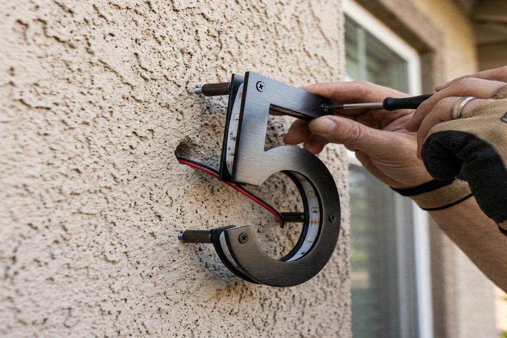
Standoff height determines halo width. Too narrow (under 8mm) and the halo becomes a thin, uneven ring. Too wide (over 20mm) and the halo diffuses into a soft wash that loses definition. The sweet spot is 10–15mm standoff height for most exterior wall textures.
Standoff Installation Sequence
- Dry-fit all anchors into the wall before connecting any wires
- Insert M6 nylon sleeve anchors (or stainless sleeve anchors for coastal environments) at each stud position
- Thread the M6 × 60mm stainless hex-head stud bolt through the anchor until flush
- Thread the standoff barrel over the stud bolt — finger-tight only at this stage
- Check level on all standoff tops with a magnetic level before final torque
- Torque standoff bolts to 4–5 Nm using a calibrated torque driver — overtorquing cracks masonry anchors
Standoff Height Reference Table
| Wall Texture | Recommended Standoff Height | Halo Width |
| Smooth render / flat cladding | 10mm | 8–10mm ring |
| Light sand texture / painted brick | 12mm | 10–12mm ring |
| Heavy rough render / exposed aggregate | 15mm | 12–15mm ring |
| Split-face stone / textured brick | 18–20mm | 15–18mm ring |
Expert Note: When torquing the M6 standoff stud bolts to the specified 4–5 Nm installation torque, a digital torque screwdriver with 0.1 Nm resolution, 0.5–10 Nm range, and audible alert at set-point is used to prevent overtorquing on the M6 × 60mm Type 316 stainless steel hex-head bolt (tensile strength grade A4-70 per ISO 3506-1). The torque-tension relationship for metric bolts in masonry anchors is governed by the anchor manufacturer’s ICC-ES evaluation report, specifically ICC-ES ESR-1917, which establishes characteristic bond and mechanical anchor values for code-compliant installations.
How Do You Connect the LED Driver to the Power Supply Without Creating a Fire Hazard?
The LED driver is the single most failure-prone component in any backlit sign installation. A correctly sized, correctly housed, and correctly wired driver lasts 10–15 years. An incorrectly specified driver creates heat, flicker, voltage drop, and — in the worst case — fire.
Driver Sizing Formula
$$P{\text{driver}} \geq (P{\text{LED/number}} \times N_{\text{numbers}}) \times 1.25$$
Where:
- $P_{\text{LED/number}}$ = wattage of each number’s LED strip (from spec sheet, typically 1.5–4W)
- $N_{\text{numbers}}$ = total number of digits/characters
- $1.25$ = 25% headroom factor to prevent thermal derating
Example: 5-digit address, each digit draws 3W → Driver must be rated ≥ $(5 \times 3W) \times 1.25 = 18.75W$ → Specify a 20W driver minimum.
Driver Wiring Connections
- AC input (primary): Black → Line (hot), White → Neutral, Green → Ground
- DC output (secondary): Red → positive bus, Black → negative bus
- Always protect the AC primary circuit with a UL-listed in-line fuse (rated at 1.5× the driver’s maximum current draw)
- Never share the neutral with another circuit — shared neutrals cause ghost illumination and GFCI nuisance trips
Expert Note: When verifying the output voltage stability of a new UL 8750-listed LED driver under full load, an oscilloscope with 200MHz bandwidth, FFT spectrum analyser, and 1MΩ input impedance is used to measure the ripple voltage on the 12V DC bus of the constant-voltage LED driver (output tolerance ±5% per UL 1310 Class 2 standard). Ripple voltage exceeding 100mV peak-to-peak causes LED flicker at frequencies detectable by high-frame-rate cameras, violating the IEEE 1789-2015 recommended practice for modulating current in high-brightness LEDs to mitigate health risks associated with stroboscopic effects.
How Do You Attach and Align Each Backlit Number for a Perfectly Level Finish?
Mounting order and alignment technique determine whether the finished sign looks hand-placed or machine-precision. Professional installers always work left-to-right, with alignment checked after every second digit.
Mounting Sequence
- With wires fed through and driver connected (but unpowered), position the first number on its standoffs
- Check horizontal level with a magnetic level held across the number top edge
- Check vertical plumb with the magnetic level held against the side face
- Only once level is confirmed: apply a 3mm bead of neutral-cure silicone to each standoff face
- Press the number onto the standoffs firmly — silicone acts as both sealant and vibration damper
- Allow silicone to skin-over (15–20 min) before moving to the next digit
- Repeat for each subsequent digit, using the first digit as the reference baseline
Spacing Formula
For a clean, professional appearance, inter-digit spacing should be:
- Minimum: 15mm between inner edges of adjacent digits
- Standard: 20–25mm (matches most manufacturer templates)
- Bold statement: 30–40mm (used for large-format 200mm+ numbers)
Expert Note: When verifying level and plumb simultaneously during backlit number mounting, a magnetic torpedo level with dual horizontal/vertical precision bubble vials (±0.5mm/m accuracy) and rare-earth magnet base is used to hold position against the brushed 316L stainless steel number face (surface flatness ≤0.2mm/100mm per ASTM A480/A480M) while hands-free silicone application proceeds. Level accuracy requirements for architectural exterior signage conform to ANSI/IES RP-20-14 Section 5.3, which specifies dimensional tolerance standards for mounted building identification signage elements.
How Do You Weatherproof All Outdoor Wire Connections on a Backlit LED Sign?
Weatherproofing failures account for the majority of premature LED sign failures. Standard twist-on wire nuts are rated for dry indoor locations only — they have no place in an outdoor backlit sign installation.
Approved Weatherproofing Methods (Outdoor Rated)
| Method | Ingress Rating | Best For | Notes |
| Silicone-filled lever connectors | IP68 | All outdoor wire junctions | Pre-filled; no installation error risk |
| Heat-shrink solder sleeves | IP67 | In-wall junctions with no access | Permanent; colour-coded |
| IP68 waterproof junction box | IP68 | Driver-to-wire interface | Use NEMA 6P or IEC 60529 IP68 rated |
| Self-amalgamating tape wrap | ~IP55 | Emergency backup only | Degrades in UV without outer conduit |
| Standard wire nuts | IP20 (dry only) | NEVER USE OUTDOORS | Will fail within 1–2 seasons |
The 4-Step Field Weatherproofing Sequence
- Strip 8mm of insulation from each conductor — use a self-adjusting stripper, not a knife
- Insert both conductors into a silicone-filled IP68 lever connector — click signals correct seating
- Apply adhesive-lined heat-shrink over the full connector body and 15mm of wire on each side
- Shrink with a heat gun at the low setting (150°C) — excessive heat (>200°C) melts silicone fill
Expert Note: When creating weatherproof wire junctions for a backlit LED house number installation, a ratchet wire crimping tool with colour-coded die set (red 22–18 AWG, blue 16–14 AWG) is used to apply non-insulated butt-splice crimp terminals rated for the conductor gauge, followed by adhesive-lined heat-shrink tubing. All crimp connectors must meet the mechanical and electrical performance requirements of UL 486A-486B (Wire Connectors), the safety standard governing electrical connections for copper conductors in wet and outdoor locations.
How Do You Troubleshoot a Backlit LED House Number That Won’t Light Up?
Follow this diagnostic sequence before replacing any component. 90% of failures resolve at Steps 1–4.
| Symptom | Test | Most Likely Cause | Fix |
| Nothing illuminates at all | Check driver AC input voltage with multimeter | No power to driver or blown fuse | Reset breaker; replace fuse |
| Some numbers lit, some not | Check DC voltage at each number’s terminals | Open wire joint in parallel run | Re-crimp the open junction |
| All numbers dim/flickering | Measure DC output voltage (should be 12V ±0.6V) | Driver overloaded or thermal shutdown | Replace undersized driver |
| Uneven halo (bright spots) | Inspect LED strip positioning inside number cavity | LED strip has shifted or come unglued | Re-seat and re-glue LED strip |
| Numbers work then fail after rain | Inspect all outdoor wire connectors for moisture | Non-waterproof connector used | Replace with IP68 silicone-fill connectors |
| Sign works in day but not at night | Check photocell/dusk sensor connection | Photocell wired in wrong orientation | Reverse photocell wiring polarity |
| Buzzing or humming noise | Listen at driver enclosure | Driver incompatible with LED load | Replace with dimmable-compatible driver |
Expert Note: When diagnosing intermittent failure in a backlit LED house number’s hidden wire run, a cable continuity tester with 4-wire Kelvin measurement mode and 200mΩ resolution is used to detect micro-resistance faults in the 18 AWG 2-conductor run (total resistance budget: ≤0.5Ω per conductor for ≤3% voltage drop at 12V DC, per NEC voltage-drop guidance in Article 210). The 4-wire Kelvin method eliminates contact resistance measurement error, following the contact resistance measurement protocol in ASTM B539-19 (Standard Test Methods for Measuring Contact Resistance of Electrical Connections).
How Do You Match Your LED Colour Temperature to Your Home’s Exterior Lighting?
Colour temperature coherence is what separates a professionally executed backlit installation from an afterthought. The halo glow must read as a deliberate design element, not a mismatched accent.
Colour Temperature Decision Guide
| Exterior Lighting Already Installed | CCT to Match | Tolerance |
| Filament-style outdoor lanterns | 2200K–2700K (amber-warm) | ±150K |
| Standard LED porch light (warm white) | 2700K–3000K | ±200K |
| Modern LED wall sconce (neutral) | 3000K–3500K | ±200K |
| Security floodlight (cool white) | 4000K–5000K | ±300K |
| No other exterior lighting | 3000K (universal neutral warm) | N/A |
The 200K Rule: The human eye detects CCT mismatches of 300K+ at close range even without direct comparison. Keep your backlit house number within 200K of the nearest visible fixture for seamless visual coherence.
Expert Note: When verifying that a replacement LED strip module’s CCT matches the existing halo lit numbers, an infrared thermal imaging camera with 320×240 pixel microbolometer array and ±2°C measurement accuracy is used to identify any LED junction temperature hotspots (junction Tj >85°C) in the COB LED module (rated per ANSI/IES LM-80-08 lumen maintenance test data). Thermal imaging identifies individual LED cells operating outside specification before CCT mismatch causes visible colour non-uniformity across the number faces, following the thermal characterisation protocol in JESD51-14 (Transient Dual Interface Method for Measurement of Thermal Resistance of Semiconductor Devices).
What Are the Most Common Backlit LED House Number Installation Mistakes to Avoid?
These are the eight errors that appear most frequently in professional sign installer call-back logs:
| Mistake | Root Cause | Consequence | Prevention |
| Template misalignment | Not using a level on the template before drilling | Numbers crooked — undoable without re-drilling | Always level and tape template, then double-check with a ruler |
| Under-specified driver | Sizing driver to exact LED wattage (no headroom) | Driver runs hot → early failure within 6–18 months | Multiply total LED wattage by 1.25 minimum |
| Standard wire nuts outdoors | Cost-cutting on connectors | Moisture ingress, corrosion, open circuit within 1–2 years | Always use IP68 silicone-filled connectors outdoors |
| No grommet at wall penetration | Skipping sleeve/grommet step | Insulation abrasion on masonry edge → short circuit | Always sleeve every wall penetration point |
| Shared neutral circuit | DIY wiring without electrician guidance | Ghost illumination, GFCI trips, potential overcurrent | Dedicated circuit from panel only |
| Standoffs overtorqued | Using a power drill instead of a torque driver | Cracked masonry anchor → number tilts over time | Use calibrated torque driver; 4–5 Nm maximum |
| Wrong standoff height for wall texture | Choosing shortest standoff for cost | Halo glow cut off by wall texture ridges | Add 3–5mm to standoff height for every 2mm of wall texture depth |
| No silicone on standoff faces | Forgetting the weatherproof step | Water ingress behind number face, corrosion, staining | Apply neutral-cure silicone bead to every standoff contact face |
Expert Note: When verifying the absence of heat buildup in an LED driver housed in a sealed outdoor enclosure, an infrared thermometer with adjustable emissivity setting (0.1–1.0) and 12:1 distance-to-spot ratio is used to measure the enclosure surface temperature of the IP65-rated polycarbonate driver enclosure (thermal conductivity: 0.19 W/m·K per ASTM E1461). Surface temperature must remain below 60°C under continuous operation to comply with the thermal management requirements of UL 8750-2009 (Standard for Safety: LED Equipment for Use in Lighting Products), which limits driver component surface temperatures to protect the LED load and prevent enclosure deformation.
How Do You Maintain and Clean Backlit LED House Numbers to Preserve the Halo Effect?
The halo glow quality degrades when the wall directly behind the number face accumulates dust, moisture staining, or biological growth. Maintaining the wall zone behind the floating numbers is as important as cleaning the number faces.
Annual Maintenance Checklist
- [ ] Inspect all standoff silicone beads for cracking, shrinkage, or colour change → re-apply if compromised
- [ ] Clean number faces with a mild detergent solution and a microfibre cloth — never abrasive pads on brushed metal
- [ ] Wipe the wall zone behind each number with a damp cloth to remove dust/biofilm
- [ ] Check all IP68 wire connectors for compression — squeeze test should feel firm, not spongy
- [ ] Verify LED output with a lux meter at 1m distance — output below 60% of original indicates LED degradation
- [ ] Inspect driver enclosure for condensation, corrosion, or insect ingress
- [ ] Re-torque standoff bolts to 4–5 Nm (thermal cycling loosens fasteners over winter–summer cycles)
Halo Effect Quality Preservation
The halo ring depends on the reflectivity of the wall surface directly behind the number. Painted walls: touch up any chips or staining. Masonry walls: apply a clear satin masonry sealant to the zone behind the numbers annually — this increases surface reflectivity by up to 15% and visibly brightens the halo without touching the LED specification.
Expert Note: When checking for UV-induced embrittlement of the silicone sealant beads around backlit LED number standoffs after seasonal exposure, a Shore A durometer with calibrated spring-loaded indenter and 0–100 HA graduated scale is used to measure the hardness of the one-part neutral-cure silicone sealant (ASTM C920 Type S, Grade NS, Class 25 rated) at each standoff contact point. A Shore A reading exceeding 65 HA indicates significant crosslink density increase from UV degradation, requiring re-application per the sealant manufacturer’s maintenance interval defined in ASTM C1193-16 (Standard Guide for Use of Joint Sealants).
🛍️ Ready to Install? Browse our full range of Backlit LED House Number Kits — 316L stainless steel, powder-coated aluminium, and brushed brass finishes. All kits include mounting template, standoffs, and UL-listed driver.
Frequently Asked Questions About Installing Backlit LED House Numbers
Do I need an electrician to install backlit LED house numbers?
In most jurisdictions, connecting the LED driver to a mains AC circuit requires a licensed electrician. The low-voltage DC side (from driver to numbers) is Class 2 and is DIY-permitted under NEC Article 725 in the US. In the UK, any new circuit from the consumer unit requires a qualified electrician under Part P of the Building Regulations.
What is the ideal standoff height for a backlit house number?
10–15mm is the professional sweet spot for smooth and lightly textured walls. For heavily textured or rough-render surfaces, add 3–5mm per 2mm of surface texture depth. Below 8mm, the halo ring becomes tight and uneven; above 20mm, the halo diffuses into a soft wash that loses sharpness.
Can I install backlit LED house numbers on a north-facing wall?
Yes — backlit house numbers are hardwired or low-voltage and are not affected by sun orientation, unlike solar signs. The only consideration on a north-facing wall (in the Northern Hemisphere) is greater moisture exposure — ensure all wire connections are IP68-rated and all wall penetrations are thoroughly silicone-sealed.
What gauge wire should I use for the low-voltage run?
18 AWG for runs up to 10 metres (33 feet); 16 AWG for runs between 10–20 metres (33–66 feet). Below 18 AWG risks excessive voltage drop — at 12V DC, a 3% drop (0.36V) causes visible dimming. Use the NEC voltage drop formula: $V{\text{drop}} = 2 \times L \times R{\text{wire}} \times I$, where $L$ is one-way run length in metres.
How do I stop the halo glow from looking uneven?
Uneven halos are caused by: LED strip positioning inside the number cavity (check it hasn’t shifted), standoff heights varying between numbers (re-measure and adjust), or wall texture varying behind different digits (add masonry sealant to the dull section). The most common fix is adding 2–3mm to the standoff height of the dim-halo number.
What is the minimum IP rating for outdoor wire connectors behind backlit numbers?
IP68 — rated for continuous immersion. The wall cavity behind a backlit number is effectively a sealed humid environment, making it harsher than an exposed outdoor location. IP65 (spray-resistant) is insufficient; only silicone-filled IP68 lever connectors or heat-shrink solder sleeves are appropriate.
Can I use a standard dimmer switch with backlit LED house numbers?
Only if the LED driver is explicitly rated as “dimmable” and the dimmer is a compatible trailing-edge (electronic) dimmer. Standard leading-edge (TRIAC) dimmers cause flickering, buzzing, and premature driver failure with most LED drivers. Check the driver specification sheet for “TRIAC dimmer compatible” or “0–10V dimming input” before wiring a dimmer into the circuit.
How long does a quality backlit LED house number installation last?
The LED components are rated for 50,000+ hours (approximately 17 years of nightly operation). The limiting factors are: the battery or driver board (8–15 years), the silicone seals (5–10 years before re-application), and the wire connectors (indefinite if IP68-rated). A correctly installed system with quality components should require no significant maintenance for 8–10 years.
Can I install backlit numbers on a rendered (stucco) wall without cracking the render?
Yes, with the right technique. Use a 4mm masonry pilot drill at very low speed to start the hole, then upsize gradually (4mm → 6mm → final diameter). Never use a hammer setting until you have confirmed the render coat is more than 20mm thick. Tape the surrounding render surface before drilling to catch any surface spall.
What causes ghost illumination in a backlit LED house number?
Ghost illumination (a faint glow when the sign should be off) is caused by: (1) a shared neutral that picks up induced voltage from adjacent circuits, (2) a leaky dimmer passing small current through the LED driver, or (3) a dusk sensor with insufficient lockout threshold. Fix by running a dedicated neutral, replacing the dimmer with a compatible model, or upgrading the dusk sensor to one with an adjustable lockout threshold.
Explore Essential House Name Plate Guides & Tutorials
Browse our comprehensive handcrafted signage guides for material care, font selection, and architectural placement:
- Beach & Airbnb Signage Design & Weatherproofing Guide (2026)
- Complete Guide to Wood House Sign Sealing & Weather Maintenance
- Horizontal vs Vertical House Numbers Layout Comparison
- Hanging & Wall-Mounted Cottage Sign Installation Guide
- Round vs Rectangular Name Plaques for Modern Property Entrances
- Best Modern & Vintage Fonts for Cottage & Residential Signs