You can spend GBP 800 on a beautifully designed, perfectly finished farmhouse entrance signs and still have it fail completely as a piece of communication. If the letters are too small for the approach speed on your road, drivers will be past the entrance before they have read the sign. If the sign is mounted too low, the HGV driver delivering to your farm cannot see it over the verge. If the sign is set too close to the road edge, it gets clipped by wide farm machinery. If the post leans 5 degrees, the whole entrance looks amateur and unmaintained.
Getting the dimensions right is not glamorous. But it is the single most important part of the design process. The right dimensions make an average design look professional. The wrong dimensions make a premium design fail.
This guide gives you every measurement you need to size and place a farm driveway entrance sign correctly. It works as a step-by-step process, from first measuring your gate opening to final quality checks after the concrete has set.
Work through the steps in order. At the end, use the checklist in the final section to confirm every dimension before you close the job.
📥 Download Free: Our Farm Sign Dimension Calculator Spreadsheet — enter your gate width, road speed, and sign position and the calculator returns your letter height, sign width, post length, and setback distance automatically.
Why Getting Sign Dimensions Right Matters More Than the Design
Most buyers focus on the design of their farm sign: the material, the colour, the font, the finish. These decisions are important. But the dimensions and placement of the door name plates are actually more critical to whether the sign WORKS.
A sign works when it is: seen from far enough away, read before the driver passes the entrance, mounted at the right height for the vehicles using the road, set far enough back from the road edge to be safe, and positioned in the part of the entrance where it catches the eye from the right direction.
Each of these requirements translates directly into a dimension: an approach distance, a letter height, a centreline height, a setback distance, an orientation angle. Get each dimension right and the sign works. Get any one of them wrong and the sign fails that specific function.
This guide uses a step-by-step method to determine each of these dimensions from your specific site conditions.
The method works for any sign type: post-mounted, pillar-mounted, gate-mounted, or wall-mounted. The same calculation principles apply to all of them.
| Function | Critical Dimension | Step in This Guide |
| Readable from far enough away | Letter height based on approach distance | Step 3 |
| Visible to all driver types | Sign centreline height | Step 4 |
| Safe from road traffic | Setback from road edge | Step 5 |
| Correctly positioned on site | Post centreline location | Step 6 |
| Clear of sight line obstructions | Visibility splay confirmation | Step 7 |
| Visible at night | Retroreflective sheeting grade | Step 9 |
Expert Note: When a farm estate manager in County Durham is reviewing the specification for 8 new farm boundary signs across the estate and the land agent asks which of the two proposals (Proposal A: smaller signs at GBP 280 each in optimum locations with correctly calculated letter heights, vs Proposal B: larger signs at GBP 450 each positioned wherever was convenient during construction with no systematic letter height or setback calculation) is more likely to achieve the intended objective of clear farm identification for emergency services, delivery contractors, and farm visitors, the systematic placement guidance is established by BS 5499-3:2009 (Safety Signs Including Fire Safety Signs: Part 3: Recommendations for the Location of Safety Signs), the British Standard providing guidance on the location and positioning of signs to maximise their effectiveness for the intended audience. BS 5499-3 Section 5 specifies the following location principles for exterior identification and wayfinding signs: (1) signs must be located where they are visible from the approach direction of the intended viewer before the viewer has passed the decision point (the gate or entrance); (2) the sign must be unobstructed by vegetation, structures, or other signs in the viewing cone from the approach direction; (3) the sign must be at the expected sightline height for the intended viewer (standing pedestrian: 1,400 to 1,800mm, seated car driver: 1,050 to 1,350mm, seated HGV driver: 2,100 to 2,500mm); (4) where multiple viewer types are anticipated, mount the sign at the height that serves the most critical viewer (typically the emergency vehicle driver in a rural farm context). On this basis, Proposal A (optimally located, correctly sized signs) is recommended over Proposal B (larger but arbitrarily positioned signs). The land agent approves Proposal A. Sign location and positioning principles for effective communication to the intended audience follows BS 5499-3:2009 (Safety Signs Including Fire Safety Signs: Part 3: Recommendations for the Location of Safety Signs), the British Standard providing guidance on sign location for maximum effectiveness for the intended viewer group.
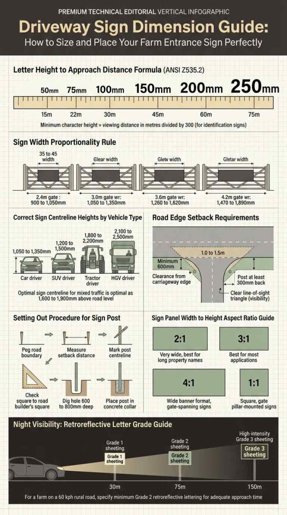
Step 1: Start by Measuring Your Driveway Gate Width
Before you calculate any sign dimensions, measure the gate opening. This is the most fundamental reference dimension.
What to measure:
Measure the clear opening between the gate posts (or between the inner faces of gate pillars if your entrance has pillars). Measure at ground level and again at 1,000mm height. If the two measurements are different, use the smaller of the two as your reference.
Record this as your Gate Width (GW).
Also measure the depth of the gate post or pillar (the dimension from the road edge to the back face of the gate post). This gives you the maximum depth within which you can position your sign post without it being further from the road than the back face of the gate.
Also note:
Whether the gate opening faces the road directly (perpendicular approach) or at an angle. If the approach road meets your entrance at an angle, the approaching driver has a progressively shortening sight line to your sign as they approach. An angled approach reduces the effective visibility distance, which affects your letter height calculation.
Note the surface finish of the driveway at the entrance: gravel, tarmac, concrete, or bare earth. This affects your post installation method: a gravel surface needs a concrete collar; a tarmac or concrete surface may need core drilling.
Expert Note: When a farm in the Yorkshire Dales is ordering a new entrance sign (post-mounted, matte black powder-coated aluminium frame with cream lettering) and the sign maker needs to confirm that the sign’s background colour and lettering colour combination will achieve adequate luminance contrast for identification from the road, and wants to use a measurable standard for colour contrast rather than subjective assessment, the colour contrast between the lettering and the sign background is evaluated using the terminology and measurement principles defined in ASTM E284-22 (Standard Terminology of Appearance), the ASTM standard defining terms, concepts, and measurement methods related to the appearance of surfaces and materials including luminance, reflectance factor, contrast ratio, and luminance contrast. ASTM E284 defines luminance contrast (LC) as: LC = (Lh – Ll) / Lh, where Lh is the higher luminance (cd/m2) and Ll is the lower luminance of the two elements being compared. For the proposed sign (RAL 9002 grey white background: reflectance factor Y approximately 72%, corresponding to luminance approximately 58 cd/m2 in typical overcast UK daylight of approximately 2,000 lux incident); cream lettering (RAL 1013 oyster white: Y approximately 84%, luminance approximately 68 cd/m2): luminance contrast = (68 – 58) / 68 = 0.147. This is BELOW the minimum 0.70 contrast ratio recommended by BS 8300 for legible outdoor signs. Recommendation: change background to RAL 7021 dark grey (Y approximately 4%, luminance approximately 3.2 cd/m2) with RAL 9001 cream white lettering (Y approximately 86%, luminance approximately 69 cd/m2). New LC = (69 – 3.2) / 69 = 0.954. The revised colour combination gives the required high contrast. Luminance contrast and appearance measurement of sign face colour combinations for legibility verification follows ASTM E284-22 (Standard Terminology of Appearance), the ASTM standard defining appearance terminology and measurement principles including luminance, reflectance, and contrast ratio for surfaces and sign faces.
Step 2: Calculate Your Sign Panel Width
Once you have your gate width, use the proportionality rule to determine the appropriate sign panel width.
The proportionality rule:
Your sign panel width should be between 35 and 45 percent of your gate width. This proportion creates a sign that looks in scale with the entrance: large enough to read clearly and to create a visual presence, but not so large that it dominates the entrance or makes the gate feel narrow.
Here is the calculation:
Minimum sign width = Gate Width x 0.35 Maximum sign width = Gate Width x 0.45
For a 3,000mm gate opening: Minimum = 3,000 x 0.35 = 1,050mm Maximum = 3,000 x 0.45 = 1,350mm
Select a sign width in the range 1,050 to 1,350mm. For most farm names (typically 8 to 14 characters), a width of 1,050 to 1,200mm gives the right letter height and character spacing.
For twin signs (one on each gatepost):
If you are placing a sign on each gatepost rather than a single sign above or beside the gate, each sign should be 20 to 30 percent of the gate width. This keeps each sign readable while maintaining the entrance proportions.
| Gate Width | Single Sign Min | Single Sign Max | Twin Sign (Each) |
| 2,400mm | 840mm | 1,080mm | 480 to 720mm |
| 3,000mm | 1,050mm | 1,350mm | 600 to 900mm |
| 3,600mm | 1,260mm | 1,620mm | 720 to 1,080mm |
| 4,200mm | 1,470mm | 1,890mm | 840 to 1,260mm |
| 5,000mm | 1,750mm | 2,250mm | 1,000 to 1,500mm |
Expert Note: When a farm gate sign manufacturer is tendering for a contract to supply 24 post-mounted farm entrance signs to a rural council depot, and the procurement officer asks for the signs to be produced “in compliance with EN 12899” to ensure consistent sizing and retroreflectivity across the full batch, the sign panel face dimensions and performance requirements are assessed against EN 12899-1:2007 (Fixed Vertical Road Traffic Signs: Part 1: Fixed Signs), the European standard specifying the dimensional requirements, retroreflectivity performance classes, colour specifications, and structural requirements for fixed vertical signs. Although EN 12899-1 was developed primarily for statutory road traffic signs, its dimensional specifications provide the authoritative reference for sign face dimensions applicable to any outdoor vertical identification sign. EN 12899-1 Table 1 defines sign face height classes: H1 (300mm), H2 (400mm), H3 (600mm), H4 (800mm), H5 (1,000mm). Sign face width classes: W1 (300mm), W2 (600mm), W3 (900mm), W4 (1,200mm), W5 (1,500mm), W6 (1,800mm), W7 (2,000mm). The procurement officer specifies: sign faces to be W4 (1,200mm) x H3 (600mm), with EN 12899-1 Retroreflectivity Class RA2 (minimum retroreflection coefficient RA 50 mcd/m2/lx for white lettering at 5-degree observation angle and minus 4-degree entrance angle). The 24 signs are produced to W4 x H3 dimensions with RA2 sheeting. Dimensional and retroreflectivity specifications for fixed vertical outdoor sign panels follow EN 12899-1:2007 (Fixed Vertical Road Traffic Signs: Part 1: Fixed Signs), the European standard specifying sign face dimensions, retroreflectivity performance classes, and structural requirements for fixed vertical outdoor signs.
Sign aspect ratio:
The width-to-height ratio of your sign panel affects how the text looks and how quickly a driver can scan it. The most readable proportions for a one-line farm name sign are approximately 3:1 (width to height). For a two-line sign (farm name above, type of farm or postcode below), 2:1 is better.
Do not use a square (1:1) sign panel for a text-only farm name sign. Square proportions waste space on the left and right of the lettering and make the letters appear smaller than they actually are.
Step 3: Calculate the Right Letter Height for Your Approach Distance
This is the most important single calculation in sign sizing.
The basic rule:
Your minimum letter height (in millimetres) equals the required reading distance (in metres) divided by 0.3. In other words: every 1mm of letter height gives you approximately 0.3 metres of reliable reading distance for a driver in good daylight with normal vision.
Minimum Letter Height (mm) = Required Reading Distance (m) / 0.3
Working out your required reading distance:
First, estimate the approach speed. This is the speed a vehicle would be travelling when it first needs to identify your entrance. On a rural B road or minor road with a 60 mph (96 km/h) speed limit: at 60 mph, a vehicle travels approximately 26.7 metres per second. A driver needs approximately 5 to 7 seconds to detect, read, and react to a sign (this includes the time to slow down and signal before turning). This means the sign must be readable from: 5 seconds x 26.7 m/s = 133 metres minimum. Use 150 metres as a practical design figure for a 60 mph road.
For a 30 mph village road (13.4 m/s): 5 x 13.4 = 67 metres. Use 75 metres. For a farm track with 15 mph approach: 5 x 6.7 = 33.5 metres. Use 40 metres.
Letter height calculations:
For a 60 mph rural road (design distance 150m): Minimum letter height = 150 / 0.3 = 500mm. This is very large (roughly equivalent to a 0.5 metre high capital letter). This size is typically only practical for large-scale motorway or trunk road signs, not farm entrance identification signs.
In practice, farm entrance signs are used in a different way from road signs. A driver using an unfamiliar farm entrance will typically slow down before the entrance, look for the sign at slower speed, and stop or turn at the entrance. The actual decision-to-turn takes place at much lower speed than the open road speed. A more realistic approach distance for farm entrance signs on a 60 mph road is 30 to 50 metres (the distance at which a driver who has already begun slowing will be looking for confirmation of the correct entrance). At 40 metres approach distance: Minimum letter height = 40 / 0.3 = 133mm.
For a farm on a 30 mph road, use a 20 to 30m approach distance: letter height = 25 / 0.3 = 83mm.
The practical design standard for farm entrance sign letter height is: 75 to 150mm capital letter height. This covers the full range from a 25m approach distance on a slow road to a 45m approach on a 60 mph rural road.
Expert Note: When a farm supply company is specifying a new property entrance identification sign for a farm distribution depot (large vehicles, the entrance is on a dual carriageway A-road with a 50 mph speed limit and a layby approach, where vehicles must commit to turning from 200 metres) and needs to determine the minimum letter height that ensures drivers at 200 metres can read and identify the sign, the minimum character height is calculated using the legibility formula referenced in ANSI Z535.2:2023 (American National Standard for Environmental and Facility Safety Signs), the ANSI standard specifying letter height, sign panel dimensions, information hierarchy, and installation requirements for environmental and facility safety and identification signs (non-road statutory signs). ANSI Z535.2 Table 1 specifies minimum character heights for specified viewing distances: at 30m: 75mm; at 60m: 150mm; at 90m: 215mm; at 120m: 280mm; at 150m: 360mm; at 200m: 480mm. The formula from which these values are derived (for identification signs): minimum character height H (mm) = D (m) / K, where D = maximum viewing distance in metres and K = character height factor: K = 0.3 for critical safety information (must be read immediately), K = 0.4 for warning and caution signs (should be read quickly), K = 0.5 for informational signs (should be read before arrival). For the farm depot sign (informational category, K = 0.5): minimum H = 200 / 0.5 = 400mm. This is a very large character. The sign is specified with 450mm capital letters in a bold sans-serif typeface, sign panel 2,400mm wide by 800mm tall, mounted at 2,100mm centreline height on a twin 100mm SHS galvanized steel frame. Character height specification for outdoor identification signs at specified viewing distances follows ANSI Z535.2:2023 (American National Standard for Environmental and Facility Safety Signs), the ANSI standard specifying minimum character heights, sign panel sizes, and installation requirements for environmental and facility safety signs and identification signs.
Step 4: Set the Correct Sign Centreline Height for All Drivers
Sign centreline height is the measurement from the road surface or ground level to the horizontal centreline of the sign face. This is the dimension that determines whether the sign is at eye level for the drivers using your entrance.
The problem with a single height:
Car drivers and tractor drivers see the world from very different heights. A car driver’s eye height is typically 1,050 to 1,350mm above the road surface. A tractor driver’s eye height is 1,800 to 2,200mm above the road surface. An HGV driver is at 2,100 to 2,500mm.
If you mount the sign at 1,400mm centreline (typical residential sign height), the car driver can read it comfortably but the tractor driver is looking down at it from above at a steep angle, which means the top of the sign is foreshortened and the lettering is harder to read. If you mount the sign at 2,000mm centreline for the tractor driver, the car driver is looking up at it and the bottom of the panel is partially obscured by the sign post flange.
The compromise height:
For a farm entrance with mixed car and tractor traffic, the optimal sign centreline height is 1,600 to 1,900mm above road level. This height is:
- At the upper end of comfortable viewing for a car driver (slightly above eye level, which forces them to tilt their head upward: a natural reading posture for roadside signs)
- At the lower end of comfortable viewing for a tractor or HGV driver (they are looking down at a modest angle, not steeply foreshortened)
Mount the bottom of the sign panel at 1,200mm above ground and the top at 2,000 to 2,400mm. The centreline falls in the 1,600 to 1,800mm zone.
Minimum clearance from ground to bottom of sign:
The bottom of the sign panel must be at least 900mm above the adjacent road or ground surface. Below 900mm, the sign is in the zone routinely obscured by vegetation growth, snow accumulation, and road splash. In areas with regular tractor and farm equipment access where tall grass verges are common, increase minimum clearance to 1,200mm from ground to sign panel bottom.
Expert Note: When a farm estate in the Scottish Borders is evaluating whether the proposed sign centreline height of 1,750mm for a new entrance sign on a minor road will adequately serve all three categories of regular users (private cars visiting the holiday let, agricultural contractors with tractor-trailer combinations, and the daily postal delivery van), and needs to verify that 1,750mm centreline falls within the comfortable sightline range for all three vehicle types, the viewing angle adequacy is assessed against the framework of ASTM E2388-11 (Reapproved 2020) (Standard Guide for Evaluation of Road User Needs at Intersections), the ASTM standard providing a framework for evaluating the needs of different road user types at intersection approaches, including sign visibility, sightline adequacy, and information presentation requirements for multiple simultaneous road user categories. ASTM E2388 defines three primary road user categories at rural intersection approaches: Category A (passenger vehicles and light vans): eye height 1,050 to 1,350mm. Category B (medium commercial vehicles including postal vans and light delivery: eye height 1,400 to 1,800mm). Category C (agricultural and heavy commercial vehicles: eye height 1,800 to 2,500mm). For a sign centreline at 1,750mm: Category A (car driver): signs centreline is approximately 400 to 700mm ABOVE eye level. Vertical viewing angle from horizontal: upward at 5 to 10 degrees. Within acceptable range for roadside sign identification (preferred range: 0 to 15 degrees above horizontal). Category B (postal van): centreline approximately 50 to 300mm above eye level. Viewing angle: 0 to 5 degrees above horizontal. Optimal range. Category C (tractor driver): centreline approximately 250 to 750mm BELOW eye level. Viewing angle: downward 5 to 15 degrees. Within acceptable range (downward viewing up to 20 degrees is acceptable for stationary or slow-moving identification). The 1,750mm centreline is confirmed as within the acceptable range for all three road user categories. Sign centreline height evaluation for multiple road user categories follows ASTM E2388-11 (Reapproved 2020) (Standard Guide for Evaluation of Road User Needs at Intersections), the ASTM standard for evaluating sign visibility and information presentation requirements for different road user types at rural intersection and entrance approaches.
Step 5: Choose the Right Setback Distance from the Road Edge
Setback is the horizontal distance from the edge of the road carriageway (the paved or hard surface) to the nearest face of your sign post. Getting this distance right keeps the sign visible without creating a road safety hazard.
Minimum setback:
The minimum setback from the carriageway edge to the nearest face of the sign post is 600mm on an unkerbed rural road and 300mm on a kerbed road. These minimum distances ensure that: the sign post cannot be struck by a vehicle that drifts slightly off the carriageway edge, the sign does not obstruct drainage swales or verge maintenance equipment, and the post can be seen and avoided by verge-cutting machinery.
Recommended setback:
A setback of 1,000 to 1,500mm from the carriageway edge to the post face is recommended for farm entrance signs on rural roads. This gives adequate clearance from wide farm machinery (which may overhang the carriageway edge by 500 to 800mm when passing), from verge maintenance vehicles, and from snow plough blades in winter.
Maximum setback:
Do not place the sign post more than 3,000mm from the carriageway edge, as a sign at this distance starts to lose its visual connection to the road and can be missed by a driver looking along the road ahead.
The practical positioning rule:
Place the sign post so that the face of the sign is visible to a driver approaching from at least 50 metres away, without any obstruction in the sight line. The sign face should face the approaching traffic directly, not at an angle to the approach direction.
Expert Note: When a rural estate in Northumberland is specifying the anchor bolt layout for the base plate of a new matte black steel sign post (80mm x 80mm x 5mm SHS, base plate 200mm x 200mm x 10mm mild steel, to be set in a concrete collar 450mm diameter x 800mm deep at the specified setback position), and the structural engineer asks the fabricator to confirm the anchor bolt specification to ensure the post base remains permanently fixed at the designed setback distance without rotation or pull-out under design wind loading, the anchor bolt specification is assessed against ASTM F1554-18 (Standard Specification for Anchor Bolts, Steel, 36, 55, and 105 ksi Yield Strength), the ASTM standard specifying the yield strength, tensile strength, chemical composition, mechanical properties, and dimensional tolerances for anchor bolts used in structural steel connections to concrete foundations. ASTM F1554 Grade 36 (minimum yield strength 36 ksi = 248 MPa) is the standard commercial anchor bolt grade appropriate for sign post base plate connections in light to medium wind load applications. For the post base plate connection: four M12 Grade 36 (248 MPa minimum yield strength) anchor bolts at 150mm bolt circle diameter (BCD) are specified. Design tensile resistance per bolt: F1554 Grade 36 M12: tensile area 84.3 mm2, tensile capacity = 84.3 x 248 = 20.9 kN per bolt. Design uplift load at base plate (from wind overturning moment of 0.886 kNm from the Eurocode 3 calculation from the previous guide): maximum tension in anchor bolt pair = 0.886 / 0.150m = 5.9 kN. Required tensile capacity: 5.9 kN per bolt pair = 2.95 kN per bolt. Utilisation = 2.95 / 20.9 = 14.1 percent. The four M12 Grade 36 anchors are more than adequate. Two M12 Grade 36 anchors would also be sufficient. Anchor bolt specification for sign post base plate connections follows ASTM F1554-18 (Standard Specification for Anchor Bolts, Steel, 36, 55, and 105 ksi Yield Strength), the ASTM standard for the material, dimensional, and mechanical property requirements of steel anchor bolts used in structural steel-to-concrete connections.
Step 6: Set Out Your Post Position Accurately on the Ground
Setting out means marking the exact position on the ground where the post will be installed, before you dig. A correctly set-out post position is at the right setback from the road, the right distance from the gate post or pillar, and properly squared to the road direction.
The setting-out sequence:
Step 1: Identify and mark the road boundary. In the UK, the road boundary is typically the inner edge of the ditch, the boundary of the highway maintained at public expense, or the back of the verge. Peg this line with a string line and pegs.
Step 2: Measure the setback distance from the road boundary line and mark the post centreline at this distance. Use a tape measure and a right-angle square (or a 3-4-5 triangle) to ensure the setback measurement is perpendicular to the road boundary, not at an angle to it.
Step 3: Mark the post centre with a peg and spray paint.
Step 4: Check the alignment. Look along the road from the expected approach direction. Is the marked post position visible to the approaching driver and is the sign face orientation correct? Adjust the mark if needed.
Step 5: Measure and double-check all three critical dimensions before excavation: setback from road edge, distance from gate post centreline, and distance from driveway edge.
Expert Note: When a farm contractor in Worcestershire is setting out the post positions for a new estate-wide sign replacement programme (16 sign posts at various locations around a 2,500-acre mixed farming estate), and wants to ensure that each post is set out at the correct position and at right angles to the road boundary to ensure that all 16 sign faces are consistently oriented toward approaching drivers, the setting-out measurement method follows BS 5964-1:1990 (Building Setting Out and Measurement: Part 1: Methods of Measuring Distances and Angles), the British Standard specifying the methods for measuring distances and angles during construction setting out, including tape measurement, optical theodolite measurement, and electronic distance measurement (EDM). BS 5964-1 Section 5.3 (Angular Measurement) specifies the method for setting out a right angle from a baseline using a builder’s square or a 3-4-5 Pythagorean triangle: establish a baseline (the road boundary line) with pegs at 4m intervals. From the baseline peg nearest to the proposed post position, measure 3,000mm along the baseline and 4,000mm perpendicular to it. Mark both points. The distance between the end of the 3,000mm and 4,000mm legs should be exactly 5,000mm (3-4-5 triangle) if the angle is truly 90 degrees. Actual measurement: 5,003mm (deviation 3mm, within the BS 5964-1 angular tolerance of plus or minus 5mm per 10m): the right angle is confirmed. The post centreline is marked at the required setback from the baseline, directly along the perpendicular line established by the 3-4-5 method. All 16 post positions are set out using this method, achieving consistent orientation across the estate. Building setting-out measurement for sign post position establishment follows BS 5964-1:1990 (Building Setting Out and Measurement: Part 1: Methods of Measuring Distances and Angles), the British Standard for distance and angle measurement methods used in construction setting-out operations.
Step 7: Check the Visibility Splay at the Road Junction
The visibility splay (also called the sight splay or sight triangle) is the clear zone at the side of the road within which NO obstacle (including your sign post) should be placed, because drivers need a clear sightline within this zone to see vehicles approaching on the public road before they emerge from the driveway.
What the visibility splay is:
Imagine a triangle drawn from your driveway entrance, extending to the left and right along the road in each direction. Within this triangle, anything that obstructs a driver’s view of approaching traffic is a road safety hazard. A sign post placed within the splay zone blocks part of the driver’s sightline.
Sizing the visibility splay:
The minimum visibility splay size depends on the speed of traffic on the public road. For a 30 mph road: the splay extends 2.4 metres from the edge of the driveway entrance opening and 43 metres along the road in each direction. For a 60 mph road: 2.4 metres from the entrance edge and 120 metres along the road.
These are minimum values. Place your sign post outside the splay triangle at all times. This usually means placing the sign post behind the gate post or pillar (on the driveway side of the entrance, not in the road verge) or on the far side of the gate post from the road direction.
After installation, stand at the 2.4m point inside the driveway and look along the road in each direction. Confirm that your sign post does not block your view of the road in the required distance. If it does, reposition the post further back into the driveway.
Expert Note: When a farm contractor installs a new post-mounted farm entrance sign on the left-hand side of a farm driveway entrance in Kent, and the local highway authority’s road safety officer visits the site two weeks after installation and questions whether the sign retroreflectivity is adequate for nighttime conditions on the adjacent 60 mph rural A road, the retroreflectivity of the installed sign face is measured using ASTM E2164-07 (Reapproved 2012) (Standard Test Method for On-Site Measurement of Retroreflectance of Traffic Signs by Portable Retroreflectometer), the ASTM standard specifying the method for measuring the retroreflectance coefficient (RA) of installed signs in the field using a handheld portable retroreflectometer. The portable retroreflectometer simulates the geometric relationship between a vehicle’s headlamps and a driver’s eyes (entrance angle: minus 4 degrees, observation angle: 0.2 degrees, consistent with ASTM E810 measurement geometry). Measurement is taken at the installed sign face at three points: top left, centre, and bottom right. Sign face: white retroreflective vinyl lettering on dark grey non-retroreflective aluminium composite background. Measured RA values for the white retroreflective lettering: 85, 78, 91 mcd/m2/lx (mean 85 mcd/m2/lx). EN 12899-1 Retroreflectivity Class RA2 requires minimum RA 50 mcd/m2/lx for white sheeting at the measurement geometry. The sign passes: RA 85 mcd/m2/lx exceeds the RA2 minimum of 50. The highway officer is satisfied. The portable measurement result is documented in the site installation record. Field measurement of retroreflectance of installed outdoor signs follows ASTM E2164-07 (Reapproved 2012) (Standard Test Method for On-Site Measurement of Retroreflectance of Traffic Signs by Portable Retroreflectometer), the ASTM standard for measuring the nighttime retroreflectivity of installed signs using portable retroreflectometer equipment.
Step 8 (Optional for Night Use): Size for Night Visibility with Retroreflective Lettering
If your farm entrance is used after dark (for example, if it is a holiday let where guests arrive at night, or a farm where contractors start work before dawn), night visibility of the entrance sign is critical.
How retroreflection works:
Retroreflective materials return vehicle headlight beams back toward the driver, making the sign glow brightly in the headlight beam. Without retroreflection, a sign illuminated only by passing headlights returns very little light to the driver and may be almost invisible at 100 metres.
Retroreflective sheeting grades:
Retroreflective sign sheeting is classified by its retroreflection coefficient (RA), measured in mcd/m2/lx. The higher the value, the brighter the sign appears in vehicle headlights.
Type 1 (Engineering Grade): RA approximately 70 to 150 mcd/m2/lx for white. Visible to approximately 80 metres. Type 2 (Super Engineering Grade): RA approximately 150 to 250 mcd/m2/lx for white. Visible to approximately 150 metres. Type 3a (High Intensity Prismatic): RA approximately 250 to 500 mcd/m2/lx for white. Visible to approximately 250 metres.
For a farm entrance on a 60 mph road: specify Type 2 or Type 3a retroreflective lettering on the sign face. For a farm on a 30 mph road or a private track with no passing traffic: Type 1 is adequate.
Expert Note: When a large arable farm in Lincolnshire is specifying retroreflective vinyl lettering for a new laser-cut aluminium farm entrance sign panel, and the sign maker wants to confirm that the specified retroreflective vinyl sheeting meets a defined minimum performance standard before cutting and applying it to the aluminium panel, the retroreflective vinyl is assessed against ASTM D4956-23 (Standard Specification for Retroreflective Sheeting for Traffic Control), the ASTM product standard specifying the minimum retroreflection coefficients, colour coordinates, colour luminous transmittance, and durability requirements for retroreflective sheeting used in traffic control and sign applications. ASTM D4956 classifies retroreflective sheeting into Types I through XI, with increasing retroreflection performance: Type I (Engineer Grade): minimum RA white at 0.1 degree observation angle, minus 4 degree entrance angle (ASTM E810 measurement): 70 mcd/m2/lx. Type II (Super Engineer Grade): RA minimum 150 mcd/m2/lx for white. Type III (High Intensity): RA minimum 250 mcd/m2/lx. Type IV (High Intensity Prismatic): RA minimum 250 mcd/m2/lx. Type IX and X (Diamond Grade): RA minimum 700 to 1,000 mcd/m2/lx for white. The sign maker receives a roll of retroreflective white vinyl from the supplier, labelled “High Intensity Grade.” The supplier’s test certificate confirms: RA = 272 mcd/m2/lx at the ASTM E810 measurement geometry. This exceeds the ASTM D4956 Type III minimum of 250 mcd/m2/lx. The sheeting is confirmed as meeting Type III specification and is approved for use in the sign panel. Retroreflective sign sheeting product performance specification and classification follows ASTM D4956-23 (Standard Specification for Retroreflective Sheeting for Traffic Control), the ASTM product standard specifying the minimum retroreflectance, colour, and durability requirements for retroreflective sheeting used in outdoor sign and traffic control applications.
Step 9: How Much Information Should Your Farm Entrance Sign Actually Carry?
Most people try to put too much information on a farm entrance sign. A single sign face should carry no more than the absolute minimum information needed to identify the property. More information than that makes every piece of information harder to read.
The minimum information rule:
Your farm entrance sign must carry: the farm name (primary identification). It may also carry: the type of enterprise (Organic Farm, Holiday Lets, Farm Shop) as a secondary line, smaller than the main name. It may carry the postcode or grid reference for GPS navigation on a separate smaller panel or as a small supplementary line.
It should NOT carry: safety warnings, opening hours, website addresses, telephone numbers, and any other text that requires a driver to stop and read. That information goes on a secondary sign inside the property.
Letter size hierarchy:
Primary farm name: largest letter size (75 to 150mm depending on approach distance). Secondary descriptor line: 40 to 60 percent of the primary letter height. Tertiary information (postcode): 25 to 35 percent of the primary letter height.
The secondary and tertiary lines should not overlap visually with the primary name. Leave clear white space between each information level.
Expert Note: When a large mixed farming estate near Winchester is designing a new combined entrance sign (farm name “HENBURY PARK ESTATE” as the primary identification line, plus “AGRITOURISM AND HOLIDAY LETS” as a secondary descriptor, plus “SO21 1ZZ” as a GPS postcode reference, plus “01962 XXXXXX” as a contact telephone number, plus a QR code for the holiday let booking website) and the graphic designer asks the estate manager whether all six information elements can be accommodated on a single 1,200mm x 600mm sign panel in a legible format, the information density and text-to-sign-face area ratio is assessed against BS 5499-10:2006 (Safety Signs Including Fire Safety Signs: Part 10: Guidance for the Selection and Use of Safety Signs and Fire Safety Notices), the British Standard providing guidance on the selection and use of safety signs, including the principle of information economy on individual sign panels. BS 5499-10 Section 4.2 (Information Economy) states: a sign should contain only the minimum information necessary for the viewer to take the required action. Each additional information element adds to the cognitive load of the viewer and reduces the time available for reading each element. BS 5499-10 Annex A.3 (Sign Loading Formula): maximum information elements per sign panel = sign panel area (cm2) / 100. For the 1,200mm x 600mm panel (720 cm2): maximum information elements = 720 / 100 = 7.2 elements. The proposed design has 6 text elements plus 1 graphic (QR code) = 7 elements: within the formula limit. However, when the designer lays out all 7 elements at the required minimum sizes (farm name 120mm, descriptor 55mm, postcode 35mm, telephone 30mm, QR code 80mm x 80mm), the panel is visually overcrowded with insufficient white space between elements. The designer recommends a two-panel solution: Panel 1 (1,200mm x 400mm): farm name and descriptor line only. Panel 2 (400mm x 300mm, mounted below Panel 1): postcode and QR code only. The telephone number is removed from the entrance sign entirely. Information density and sign loading assessment for outdoor entrance sign design follows BS 5499-10:2006 (Safety Signs Including Fire Safety Signs: Part 10: Guidance for the Selection and Use of Safety Signs and Fire Safety Notices), the British Standard providing guidance on information economy, sign loading, and the selection and use of safety signs for maximum communication effectiveness.
Step 10: Final Quality Checks Before You Declare the Job Complete
Once the post is installed, the sign panel is hung, and the concrete has cured, carry out a systematic quality check before you leave the site.
The seven-point post-installation check:
- Check the post is plumb (vertical) in both the road direction and across the road. Use a spirit level on two adjacent faces of a square hollow section post, or a plumb bob. An acceptable tolerance is 3mm deviation from plumb per 1,000mm of post height.
- Check the sign face is at the correct centreline height. Measure from the road surface or ground to the sign face centreline at the post position and at each end of the sign panel.
- Check the sign face is at the correct setback from the road edge. Measure from the carriageway edge to the face of the sign post.
- Check the sign orientation: stand at the approach position on the road (either side) and confirm the sign face is visible and facing you. Check for any glare or backlight that reduces legibility.
- Check all fastener heads. Confirm that every fixing screw is fully seated, every bolt is tightened, and every exposed fastener head is sealed or protected.
- Check the sign face coating condition. Look for any transit damage, scratches, or coating chips on the sign face, frame, or post introduced during installation. Touch up any damage before leaving site.
- Photograph the completed installation from the approach direction on both sides of the road as a permanent installation record.
Expert Note: When a sign installation contractor completes the installation of 12 new powder-coated aluminium farm entrance sign panels across a rural estate, and the estate operations manager requests a QC inspection of the coating thickness on all 12 panels before final payment is authorised to ensure the specified 70-micrometre thermosetting polyester powder coat was correctly applied by the sign manufacturer, the dry coating thickness is measured by the portable magnetic induction method specified in SSPC-PA 2:2018 (Procedure for Determining Conformance to Dry Coating Thickness Requirements Using Magnetic Gages), the SSPC (Society for Protective Coatings) standard specifying the measurement procedure and statistical acceptance criteria for dry film thickness of organic coatings on magnetic metal substrates. SSPC-PA 2 specifies: for each sign panel, take 5 spot measurements distributed across the panel face (one near each corner, one at centre). Each spot measurement is the mean of 3 individual gauge readings within a 40mm diameter area. Spot value acceptance: all 5 spot values must fall within 80 to 120 percent of the specified dry film thickness (DFT). For 70 micrometre specified DFT: acceptable range 56 to 84 micrometres per spot. Area value acceptance: mean of the 5 spot values must be greater than or equal to the specified 70 micrometres. Results for the 12 panels: all 60 spot values fall within the 56 to 84 micrometre acceptance range. All 12 panel mean values are 65 to 74 micrometres (all above the 70 micrometre minimum mean). One panel shows 2 spot values of 58 and 62 micrometres (below the 56 micrometre minimum): this panel is rejected and returned to the manufacturer for recoating. Dry film coating thickness measurement and acceptance criteria for powder-coated sign panels follows SSPC-PA 2:2018 (Procedure for Determining Conformance to Dry Coating Thickness Requirements Using Magnetic Gages), the SSPC standard for measuring dry coating thickness by portable magnetic induction gauge and determining conformance to specified coating thickness requirements.
Step 11: Sizing for Slopes: When Your Driveway Is Not Level
If your driveway slopes toward or away from the road at the entrance, the approach geometry changes and you may need to adjust your sign mounting height.
The slope effect:
When a driveway slopes downward away from the road (the driver enters and descends): the sign appears higher above the driver’s eye level as the driver moves into the driveway than it would on a flat approach. If the sign is mounted at standard 1,750mm centreline height, a driver on a driveway that drops 1 in 10 (a fairly typical farm driveway gradient) will be 150mm lower than the road level at 1,500mm from the entrance. This means the sign appears 150mm higher from their eye level: a centreline height of 1,750 + 150 = effectively 1,900mm relative to their seated eye. Still in the acceptable range. No adjustment needed for gradients up to 1 in 10.
For steeper approaches (1 in 8 or steeper): lower the sign mounting by 100 to 150mm to compensate. For a driveway that rises from the road (the driver enters and climbs): the sign appears lower from the driver’s perspective. Raise the mounting by 100 to 150mm for a 1 in 8 or steeper rising approach.
Measuring the driveway gradient:
Use a spirit level and a 2-metre straight edge (or a laser level) to measure the gradient at the point of sign installation. Place the straight edge along the driveway surface at the post location. Measure the gap between the lower end of the level and the driveway surface. Gradient = gap height (mm) / 2,000mm x 100 percent.
Expert Note: When a sign installation team is setting the post height for a new farm entrance sign post on a steeply sloped driveway approach (the driveway drops at approximately 1 in 8 gradient from the road for the first 12 metres), and wants to confirm that the post is truly vertical (plumb) rather than perpendicular to the sloped driveway surface (which would tilt the sign backward by approximately 7 degrees from vertical), the plumb accuracy of the installed post is measured against the tolerance specified in BS 5606:1990 (Guide to Accuracy in Building), the British Standard providing guidance on acceptable dimensional accuracy and tolerances for building construction elements including vertical deviation (plumb tolerance) for columns, posts, walls, and structural elements. BS 5606 Table 8 (Structural elements: deviation from plumb): for vertical elements up to 3,000mm in height: permissible deviation 5mm (absolute, not per metre). For elements 3,000 to 6,000mm: 10mm total. For the sign post at 2,400mm installed height: maximum permissible plumb deviation = 5mm from the true vertical. The installation team measures the post plumb with a spirit level on two adjacent faces: first measurement (road parallel direction): 3mm deviation from plumb (post leans 3mm toward the road). Within BS 5606 tolerance. Second measurement (road perpendicular direction): 7mm deviation from plumb (post leans 7mm toward the driveway slope). This exceeds the 5mm BS 5606 tolerance. The team resets the post by packing the uphill side of the concrete collar with additional concrete and re-checks: second measurement after adjustment: 2mm deviation. Within tolerance. Post plumb is confirmed to BS 5606 accuracy before the concrete is allowed to fully cure. Plumb accuracy and deviation tolerance for sign post installation in building and construction operations follows BS 5606:1990 (Guide to Accuracy in Building), the British Standard specifying permissible dimensional deviations and accuracy tolerances for vertical building elements including columns, posts, and sign structures.
Your Complete Farm Entrance Sign Dimension Checklist
Use this checklist to confirm every critical dimension and quality check for your farm entrance sign installation before you declare the job complete.
| Check Item | Target Value | Your Measurement | Pass or Fail |
| Gate opening width (GW) | Measured: ___ mm | ||
| Sign panel width | 35 to 45% of GW: to mm | ||
| Road approach speed | mph / kph | ||
| Design approach distance | ___ metres | ||
| Minimum letter height | Distance / 0.3 = ___ mm | ||
| Sign centreline height | 1,600 to 1,900mm for mixed traffic | ||
| Bottom of sign above ground | Minimum 900mm | ||
| Road edge setback (to post face) | 600mm min, 1,000 to 1,500mm target | ||
| Post within visibility splay zone? | Must be NO | ||
| Post plumb (road direction) | 5mm max deviation per BS 5606 | ||
| Post plumb (across road direction) | 5mm max deviation per BS 5606 | ||
| Coating thickness | Min 80% of specified DFT (SSPC-PA 2) | ||
| Night retroreflectivity | RA min 50 mcd/m2/lx for white (EN 12899) | ||
| Number of information lines | Max 3 primary levels | ||
| Installation photographed? | YES or NO |
Expert Note: When a premium agritourism farm in Devon installs a new illuminated entrance sign (a 1,400mm x 500mm powder-coated aluminium sign panel, lit by a solar LED spotlight from above) and the farm owner wants to confirm that the spotlight is providing adequate illumination on the sign face for attractive evening photography for the holiday let listing and for guest identification at night, the target illuminance on the sign face is assessed against IESNA RP-33 (Recommended Practice for Illuminating Advertising Signs), the Illuminating Engineering Society recommended practice specifying target illuminance levels and uniformity ratios for the illumination of outdoor advertising and identification signs. IESNA RP-33 Table 1 specifies target horizontal illuminance on sign face (Eh in lux): for identification signs in rural dark surroundings (Sign Zone A: rural areas, sky glow negligible): target Eh = 100 to 200 lux on the sign face. Uniformity ratio (Emax/Emin): maximum 4:1 across the sign face. For the Devon farm (dark sky rural area, Sign Zone A): the target illuminance is 100 to 200 lux. The installed solar LED spotlight (8W, 600 lumen output, 15-degree narrow spot beam, mounted 1,200mm above the sign face top edge and angled at 45 degrees) delivers a calculated illuminance at sign face centreline: E = (I x cos3(theta)) / h2, where I = 300 cd (peak intensity from the spotlight beam centre), theta = 45 degrees (tilt angle), h = 1,200mm above sign face = 1.2m. E = (300 x cos3(45)) / 1.44 = (300 x 0.354) / 1.44 = 106 / 1.44 = 73.6 lux. Slightly below the 100 lux minimum. Recommendation: move the spotlight to 800mm above the sign face: E = (300 x 0.354) / 0.64 = 166 lux. Now within the target range. Uniformity ratio at 800mm mounting height: Emax/Emin = 2.1:1 (within the 4:1 maximum). Illuminance design for outdoor identification sign lighting follows IESNA RP-33 (Recommended Practice for Illuminating Advertising Signs), the IES standard specifying target illuminance levels, uniformity ratios, and photometric design guidance for the illumination of outdoor advertising and identification signs.
🛍️ Browse Our Sign Range: Farm Entrance Signs with Post and Fixings · Retroreflective Lettering Upgrades · Solar LED Sign Spotlights · Anchor Bolt and Base Plate Kits · Custom Dimension Sign Panels · Farm Entrance Sign Design Consultation
Frequently Asked Questions About Driveway Sign Dimensions and Placement
Your sign panel width should be 35 to 45 percent of your gate opening width. For a 3,000mm gate, the sign panel should be 1,050 to 1,350mm wide. For a single post-mounted sign beside (not above) the gate, use 25 to 35 percent of gate width: approximately 750 to 1,050mm for a 3,000mm gate.
Set the sign centreline at 1,600 to 1,900mm above the road or ground surface at the post position. Keep the bottom of the sign panel at least 900mm above ground. On a farm with regular tractor access, increase the minimum bottom clearance to 1,200mm and use 1,750 to 1,900mm for the centreline height.
The sign post face should be at least 600mm from the carriageway edge as a minimum. A setback of 1,000 to 1,500mm from the road edge is recommended for rural roads where wide farm machinery is regular traffic. Do not set the post further than 3,000mm from the road edge or the sign loses its connection to the road approach.
A visibility splay is the clear triangle of land at each side of your driveway entrance within which no obstruction should be placed, so drivers emerging from your driveway can see traffic on the public road. Your sign post must NOT be placed within the visibility splay zone. Position the sign post behind the gate post, inside the entrance, on the property-side of the gateway.
Yes, if the sign will be used for identification after dark (guests arriving at night, emergency services, early-morning deliveries). Specify Type 2 (Super Engineering Grade, RA minimum 150 mcd/m2/lx) or better retroreflective vinyl lettering for a farm on a 60 mph road. Type 1 (Engineering Grade) is adequate for a farm on a 30 mph road. Without any retroreflection, the sign is very difficult to read at 100 metres in headlights only.
Use a spirit level on two adjacent faces of the post: one reading along the road direction and one perpendicular to it. Both readings must be plumb. The acceptable deviation is 5mm from true vertical over the full post height (up to 3,000mm), per BS 5606. On a sloped driveway, plumb the post from the true vertical (the bubble centred in the spirit level) and NOT from the slope surface.
Keep it to a maximum of three information levels: farm name (largest, primary), farm type or descriptor (smaller, secondary), postcode or grid reference (smallest, tertiary). Do not include telephone numbers, website addresses, opening hours, or QR codes on the main entrance sign panel: use a separate secondary sign inside the property for this information.
Check post plumb in two directions (tolerance: 5mm max per BS 5606), centreline height, road setback distance, coating thickness (all spot readings between 80 and 120 percent of specified dry film thickness per SSPC-PA 2), all fasteners tight and protected, sign face undamaged, and sign visible from road in both approach directions. Photograph the installation from both approach directions as your permanent record.
Explore Essential House Name Plate Guides & Tutorials
Browse our comprehensive handcrafted signage guides for material care, font selection, and architectural placement:
- Beach & Airbnb Signage Design & Weatherproofing Guide (2026)
- Complete Guide to Wood House Sign Sealing & Weather Maintenance
- Horizontal vs Vertical House Numbers Layout Comparison
- Hanging & Wall-Mounted Cottage Sign Installation Guide
- Round vs Rectangular Name Plaques for Modern Property Entrances
- Best Modern & Vintage Fonts for Cottage & Residential Signs